Description
NTN 32028XU Single Row Tapered Roller Bearing (Inside Dia - 140mm, Outside Dia - 210mm)
SPECIFICATIONS
| Type of Product : |
Single Row Tapered Roller Bearing |
| Inside Diameter (d) (mm) : |
140 |
| Outside Diameter D (mm) : |
210 |
| Width Dia mm : |
45 |
| Model No : |
32028XU |

1. Types, design features, and characteristics
Tapered roller bearings are designed so the tapered vertex of the raceway surfaces of the inner and outer rings and rollers converge at one point on the centerline of the bearing (see Fig. 1).
The tapered rollers are guided by the compound force of the inner and outer raceway surfaces which keep the rollers pressed up against the large rib on the inner ring.
A large variety of these bearings, including single, double, and four row arrangements, are available in both metric and inch series. Each
type and associated characteristics are shown in Table 1. For four-row tapered roller bearings, see section “C. Special application bearings.”
Table 1 Tapered roller bearing types and characteristics
| Type |
Characteristics |
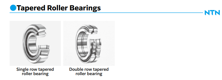
Single row tapered
roller bearings |
(1) There are both metric and inch series adhering to the standards shown in the following table. Dimension series

*Dimension series previously not covered by 3XX are regulated under JIS B 1512; dimensions previously missing from 3XX will henceforth use the bearing number.
(2) In addition to the standard design, there are also medium contact angle and large contact angle types, denoted by the contact angle codes at the end of the part numbers (C and D, respectively).
(3) Subunits
Tapered roller bearings can be disassembled into parts: the inner ring, rollers, and cage (collectively known as the “CONE”) and the outer ring (known as the “CUP”). These are the bearing’s “subunits”. Subunit dimensions are standardized under ISO or ABMA standards, and unified subunits are interchangeable within each dimensional standard. However, high precision grade bearings are generally not interchangeable, and these subunits must be used by assembling only subunits with identical manufacturing numbers.
Aside from any cautionary notes that may appear, the single row tapered roller bearings listed in the dimension tables have subunits standardized for both metric and inch systems (including J series). (Refer to Fig. 2)

|
Single row tapered
roller bearings |
(4) These bearings are constructed to have a high capacity for radial loads, axial loads, and combined loads. The larger the contact angle, the greater the axial load capacity. When a pure radial load is applied to a tapered roller bearing, an induced load in the axial direction is also generated, so these bearings are generally used in pairs.
(5) Single row tapered roller bearings are separable, so both the inner and outer rings can be used with tight fits.
(6) Tapered roller bearings are also manufactured with flanges attached to the outer rings. For more details, contact NTN Engineering. (Refer to Fig. 3)

|
| Duplex tapered roller bearings |
(1) When two single-row tapered roller bearings are to be used in combination, the bearing clearance and preload are adjusted by the inner ring spacer or the outer ring spacer (see Fig. 4).
(2) A product number and a combination code are indicated on inner rings, outer rings, and spacers. Parts displaying the same number and code must be used in combination.
(3) See A-96 Table 8.14 for the axial internal clearance.

|
Double row tapered
roller bearings |
(1) Back-to-back arrangement (using double row outer rings) and face-to-face arrangement (using double row inner rings) are both available. The assemblies have been adjusted so that each type's internal clearance values are fixed. Only parts with identical manufacturing numbers can be used and they must be assembled according to their code numbers. (Refer to Fig. 5)
(2) See A-96 Table 8.14 for the axial internal clearance of double-row and duplex bearings.

|
2. Standard cage type
In general, pressed cages (see Fig. 6) are used in tapered roller bearings. For large sized bearings, machined or pin type cages may also be used, while resin cages may also be used for smaller sized bearings.

3. Allowable misalignment
In order to avoid edge loading and potential for premature failure, the maximum allowable misalignment based on bearing series can be found below.
The allowable misalignment of combined bearings is influenced by the load center position, so please consult NTN Engineering.
• Single row (standard) …………… 1/ 2 000
• Single row (ULTAGE) …………… 1/ 600
4. Precautions
If bearing load is light during operation, or if the ratio of axial to radial load for duplex and double row bearings exceeds the value of e, slipping may develop between the rollers and raceway surface, sometimes resulting in smearing. The mass of rollers and cages particularly tends to be large for large tapered roller bearings. For additional details, please contact NTN Engineering.
In tapered roller bearings, the cage may protrude beyond the inner and/or outer ring side faces. Care should be taken when designing the housing and shaft to ensure contact with the cage does not occur.

