BEARING / FA

NSK NSK Tapered Roller Bearings, Single-Row Metric Design HR30232J ,D=160
NSK Tapered Roller Bearings, Single-Row Metric Design HR30232J ,D=160 Bearing Numbers Boundary Dimensions (mm) Basic Load Ratings (kN) Limiting Speeds (min-1) ISO355 Dimensions Series approx. Constant e Axial Load Factors Mass (kg) approx. d D T B C Cone r min. Cup r min. Cr C0r Grease Oil Y1 Y0 HR30232J 160 290 52 48 40 4 3 530 730 1200 1600 4GB 0.44 1.4 0.76 13.7 DESIGN, TYPES, AND FEATURES Tapered roller bearings are designed so the apices of the cones formed by the raceways of the inner and outer rings and the inner ring rollers all coincide at one point on the axis of the bearing. When a radial load is imposed, a component axial force occurs; therefore, it is necessary to use two bearings in opposition or some other multiple-bearing arrangement. For Metric Series medium-angle or steep-angle tapered roller bearings, the respective contact angle designation C or D is added after the bore number. For normal-angle tapered roller bearings, no contact angle designation is used. Medium-angle tapered roller bearings are primarily used for the pinion shafts of differential gears in automobiles. Some bearings with high load capacity (HR Series) contain a J suffix that indicates they conform to ISO specifications for outer ring back face raceway diameter, outer ring width, and contact angle. Therefore, the inner ring assembly and outer ring of bearings with a J suffix are internationally interchangeable. Some Metric Series tapered roller bearings specified by ISO 355 have different dimensions from past Series 3XX bearings. Some of these are listed in the bearing tables. These conform to ISO specifications for the small-end diameter of the inner ring and contact angle. The inner and outer ring assemblies are internationally interchangeable. The bearing designation structure, which has changed from the past, is listed below: Inch Series bearings also exist. Inner ring assemblies and outer rings are approximately formulated as follows (excluding four-row tapered roller bearings): Various arrangements of tapered roller bearings (excluding single-row bearings) are available. The cages of tapered roller bearings are usually made of pressed steel. Table 1 Design and Features of Tapered Roller Bearing Arrangements Design Arrangement Ex. Bearing Designation Features Back-to-back HR30210JDB+KLR10 Two standard bearings are combined. The bearing clearances are adjusted by inner ring spacers or outer ring spacers. The inner rings, outer rings, and spacers are marked with serial numbers and mating marks. Components with the same serial number can be assembled by referring to the matching indications. Face-to-face HR30210JDF+KR KBE Type 100KBE31+L The KBE type is a back-to-back arrangement of bearings with an integrated outer ring spacer. The KH type is a face-to-face arrangement in which the inner rings are integrated. Since the bearing clearance is adjusted using spacers, components must have the same serial number for assembly with reference to the matching indications. KH Type 110KH31+K
$1,470.88

NSK NSK Tapered Roller Bearings, Single-Row Metric Design HR30230J ,D=150
NSK Tapered Roller Bearings, Single-Row Metric Design HR30230J ,D=150 Bearing Numbers Boundary Dimensions (mm) Basic Load Ratings (kN) Limiting Speeds (min-1) ISO355 Dimensions Series approx. Constant e Axial Load Factors Mass (kg) approx. d D T B C Cone r min. Cup r min. Cr C0r Grease Oil Y1 Y0 HR30230J 150 270 49 45 38 4 3 485 665 1300 1800 2GB 0.44 1.4 0.76 11.2 DESIGN, TYPES, AND FEATURES Tapered roller bearings are designed so the apices of the cones formed by the raceways of the inner and outer rings and the inner ring rollers all coincide at one point on the axis of the bearing. When a radial load is imposed, a component axial force occurs; therefore, it is necessary to use two bearings in opposition or some other multiple-bearing arrangement. For Metric Series medium-angle or steep-angle tapered roller bearings, the respective contact angle designation C or D is added after the bore number. For normal-angle tapered roller bearings, no contact angle designation is used. Medium-angle tapered roller bearings are primarily used for the pinion shafts of differential gears in automobiles. Some bearings with high load capacity (HR Series) contain a J suffix that indicates they conform to ISO specifications for outer ring back face raceway diameter, outer ring width, and contact angle. Therefore, the inner ring assembly and outer ring of bearings with a J suffix are internationally interchangeable. Some Metric Series tapered roller bearings specified by ISO 355 have different dimensions from past Series 3XX bearings. Some of these are listed in the bearing tables. These conform to ISO specifications for the small-end diameter of the inner ring and contact angle. The inner and outer ring assemblies are internationally interchangeable. The bearing designation structure, which has changed from the past, is listed below: Inch Series bearings also exist. Inner ring assemblies and outer rings are approximately formulated as follows (excluding four-row tapered roller bearings): Various arrangements of tapered roller bearings (excluding single-row bearings) are available. The cages of tapered roller bearings are usually made of pressed steel. Table 1 Design and Features of Tapered Roller Bearing Arrangements Design Arrangement Ex. Bearing Designation Features Back-to-back HR30210JDB+KLR10 Two standard bearings are combined. The bearing clearances are adjusted by inner ring spacers or outer ring spacers. The inner rings, outer rings, and spacers are marked with serial numbers and mating marks. Components with the same serial number can be assembled by referring to the matching indications. Face-to-face HR30210JDF+KR KBE Type 100KBE31+L The KBE type is a back-to-back arrangement of bearings with an integrated outer ring spacer. The KH type is a face-to-face arrangement in which the inner rings are integrated. Since the bearing clearance is adjusted using spacers, components must have the same serial number for assembly with reference to the matching indications. KH Type 110KH31+K
$1,236.16

NSK NSK Tapered Roller Bearings, Single-Row Metric Design HR30228J ,D=140
NSK Tapered Roller Bearings, Single-Row Metric Design HR30228J ,D=140 Bearing Numbers Boundary Dimensions (mm) Basic Load Ratings (kN) Limiting Speeds (min-1) ISO355 Dimensions Series approx. Constant e Axial Load Factors Mass (kg) approx. d D T B C Cone r min. Cup r min. Cr C0r Grease Oil Y1 Y0 HR30228J 140 250 45.75 42 36 4 3 390 515 1400 1900 4FB 0.44 1.4 0.76 8.74 DESIGN, TYPES, AND FEATURES Tapered roller bearings are designed so the apices of the cones formed by the raceways of the inner and outer rings and the inner ring rollers all coincide at one point on the axis of the bearing. When a radial load is imposed, a component axial force occurs; therefore, it is necessary to use two bearings in opposition or some other multiple-bearing arrangement. For Metric Series medium-angle or steep-angle tapered roller bearings, the respective contact angle designation C or D is added after the bore number. For normal-angle tapered roller bearings, no contact angle designation is used. Medium-angle tapered roller bearings are primarily used for the pinion shafts of differential gears in automobiles. Some bearings with high load capacity (HR Series) contain a J suffix that indicates they conform to ISO specifications for outer ring back face raceway diameter, outer ring width, and contact angle. Therefore, the inner ring assembly and outer ring of bearings with a J suffix are internationally interchangeable. Some Metric Series tapered roller bearings specified by ISO 355 have different dimensions from past Series 3XX bearings. Some of these are listed in the bearing tables. These conform to ISO specifications for the small-end diameter of the inner ring and contact angle. The inner and outer ring assemblies are internationally interchangeable. The bearing designation structure, which has changed from the past, is listed below: Inch Series bearings also exist. Inner ring assemblies and outer rings are approximately formulated as follows (excluding four-row tapered roller bearings): Various arrangements of tapered roller bearings (excluding single-row bearings) are available. The cages of tapered roller bearings are usually made of pressed steel. Table 1 Design and Features of Tapered Roller Bearing Arrangements Design Arrangement Ex. Bearing Designation Features Back-to-back HR30210JDB+KLR10 Two standard bearings are combined. The bearing clearances are adjusted by inner ring spacers or outer ring spacers. The inner rings, outer rings, and spacers are marked with serial numbers and mating marks. Components with the same serial number can be assembled by referring to the matching indications. Face-to-face HR30210JDF+KR KBE Type 100KBE31+L The KBE type is a back-to-back arrangement of bearings with an integrated outer ring spacer. The KH type is a face-to-face arrangement in which the inner rings are integrated. Since the bearing clearance is adjusted using spacers, components must have the same serial number for assembly with reference to the matching indications. KH Type 110KH31+K
$1,041.02

NSK NSK Tapered Roller Bearings, Single-Row Metric Design HR30226J ,D=130
NSK Tapered Roller Bearings, Single-Row Metric Design HR30226J ,D=130 Bearing Numbers Boundary Dimensions (mm) Basic Load Ratings (kN) Limiting Speeds (min-1) ISO355 Dimensions Series approx. Constant e Axial Load Factors Mass (kg) approx. d D T B C Cone r min. Cup r min. Cr C0r Grease Oil Y1 Y0 HR30226J 130 230 43.75 40 34 4 3 375 505 1500 2000 4FB 0.44 1.4 0.76 7.25 DESIGN, TYPES, AND FEATURES Tapered roller bearings are designed so the apices of the cones formed by the raceways of the inner and outer rings and the inner ring rollers all coincide at one point on the axis of the bearing. When a radial load is imposed, a component axial force occurs; therefore, it is necessary to use two bearings in opposition or some other multiple-bearing arrangement. For Metric Series medium-angle or steep-angle tapered roller bearings, the respective contact angle designation C or D is added after the bore number. For normal-angle tapered roller bearings, no contact angle designation is used. Medium-angle tapered roller bearings are primarily used for the pinion shafts of differential gears in automobiles. Some bearings with high load capacity (HR Series) contain a J suffix that indicates they conform to ISO specifications for outer ring back face raceway diameter, outer ring width, and contact angle. Therefore, the inner ring assembly and outer ring of bearings with a J suffix are internationally interchangeable. Some Metric Series tapered roller bearings specified by ISO 355 have different dimensions from past Series 3XX bearings. Some of these are listed in the bearing tables. These conform to ISO specifications for the small-end diameter of the inner ring and contact angle. The inner and outer ring assemblies are internationally interchangeable. The bearing designation structure, which has changed from the past, is listed below: Inch Series bearings also exist. Inner ring assemblies and outer rings are approximately formulated as follows (excluding four-row tapered roller bearings): Various arrangements of tapered roller bearings (excluding single-row bearings) are available. The cages of tapered roller bearings are usually made of pressed steel. Table 1 Design and Features of Tapered Roller Bearing Arrangements Design Arrangement Ex. Bearing Designation Features Back-to-back HR30210JDB+KLR10 Two standard bearings are combined. The bearing clearances are adjusted by inner ring spacers or outer ring spacers. The inner rings, outer rings, and spacers are marked with serial numbers and mating marks. Components with the same serial number can be assembled by referring to the matching indications. Face-to-face HR30210JDF+KR KBE Type 100KBE31+L The KBE type is a back-to-back arrangement of bearings with an integrated outer ring spacer. The KH type is a face-to-face arrangement in which the inner rings are integrated. Since the bearing clearance is adjusted using spacers, components must have the same serial number for assembly with reference to the matching indications. KH Type 110KH31+K
$808.14

NSK NSK Tapered Roller Bearings, Single-Row Metric Design HR30224J ,D=120
NSK Tapered Roller Bearings, Single-Row Metric Design HR30224J ,D=120 Bearing Numbers Boundary Dimensions (mm) Basic Load Ratings (kN) Limiting Speeds (min-1) ISO355 Dimensions Series approx. Constant e Axial Load Factors Mass (kg) approx. d D T B C Cone r min. Cup r min. Cr C0r Grease Oil Y1 Y0 HR30224J 120 215 43.5 40 34 3 2.5 335 450 1600 2200 4FB 0.44 1.4 0.76 6.28 DESIGN, TYPES, AND FEATURES Tapered roller bearings are designed so the apices of the cones formed by the raceways of the inner and outer rings and the inner ring rollers all coincide at one point on the axis of the bearing. When a radial load is imposed, a component axial force occurs; therefore, it is necessary to use two bearings in opposition or some other multiple-bearing arrangement. For Metric Series medium-angle or steep-angle tapered roller bearings, the respective contact angle designation C or D is added after the bore number. For normal-angle tapered roller bearings, no contact angle designation is used. Medium-angle tapered roller bearings are primarily used for the pinion shafts of differential gears in automobiles. Some bearings with high load capacity (HR Series) contain a J suffix that indicates they conform to ISO specifications for outer ring back face raceway diameter, outer ring width, and contact angle. Therefore, the inner ring assembly and outer ring of bearings with a J suffix are internationally interchangeable. Some Metric Series tapered roller bearings specified by ISO 355 have different dimensions from past Series 3XX bearings. Some of these are listed in the bearing tables. These conform to ISO specifications for the small-end diameter of the inner ring and contact angle. The inner and outer ring assemblies are internationally interchangeable. The bearing designation structure, which has changed from the past, is listed below: Inch Series bearings also exist. Inner ring assemblies and outer rings are approximately formulated as follows (excluding four-row tapered roller bearings): Various arrangements of tapered roller bearings (excluding single-row bearings) are available. The cages of tapered roller bearings are usually made of pressed steel. Table 1 Design and Features of Tapered Roller Bearing Arrangements Design Arrangement Ex. Bearing Designation Features Back-to-back HR30210JDB+KLR10 Two standard bearings are combined. The bearing clearances are adjusted by inner ring spacers or outer ring spacers. The inner rings, outer rings, and spacers are marked with serial numbers and mating marks. Components with the same serial number can be assembled by referring to the matching indications. Face-to-face HR30210JDF+KR KBE Type 100KBE31+L The KBE type is a back-to-back arrangement of bearings with an integrated outer ring spacer. The KH type is a face-to-face arrangement in which the inner rings are integrated. Since the bearing clearance is adjusted using spacers, components must have the same serial number for assembly with reference to the matching indications. KH Type 110KH31+K
$695.94

NSK NSK Tapered Roller Bearings, Single-Row Metric Design HR30222J ,D=110
NSK Tapered Roller Bearings, Single-Row Metric Design HR30222J ,D=110 Bearing Numbers Boundary Dimensions (mm) Basic Load Ratings (kN) Limiting Speeds (min-1) ISO355 Dimensions Series approx. Constant e Axial Load Factors Mass (kg) approx. d D T B C Cone r min. Cup r min. Cr C0r Grease Oil Y1 Y0 HR30222J 110 200 41 38 32 3 2.5 315 420 1800 2400 3FB 0.42 1.4 0.79 5.28 DESIGN, TYPES, AND FEATURES Tapered roller bearings are designed so the apices of the cones formed by the raceways of the inner and outer rings and the inner ring rollers all coincide at one point on the axis of the bearing. When a radial load is imposed, a component axial force occurs; therefore, it is necessary to use two bearings in opposition or some other multiple-bearing arrangement. For Metric Series medium-angle or steep-angle tapered roller bearings, the respective contact angle designation C or D is added after the bore number. For normal-angle tapered roller bearings, no contact angle designation is used. Medium-angle tapered roller bearings are primarily used for the pinion shafts of differential gears in automobiles. Some bearings with high load capacity (HR Series) contain a J suffix that indicates they conform to ISO specifications for outer ring back face raceway diameter, outer ring width, and contact angle. Therefore, the inner ring assembly and outer ring of bearings with a J suffix are internationally interchangeable. Some Metric Series tapered roller bearings specified by ISO 355 have different dimensions from past Series 3XX bearings. Some of these are listed in the bearing tables. These conform to ISO specifications for the small-end diameter of the inner ring and contact angle. The inner and outer ring assemblies are internationally interchangeable. The bearing designation structure, which has changed from the past, is listed below: Inch Series bearings also exist. Inner ring assemblies and outer rings are approximately formulated as follows (excluding four-row tapered roller bearings): Various arrangements of tapered roller bearings (excluding single-row bearings) are available. The cages of tapered roller bearings are usually made of pressed steel. Table 1 Design and Features of Tapered Roller Bearing Arrangements Design Arrangement Ex. Bearing Designation Features Back-to-back HR30210JDB+KLR10 Two standard bearings are combined. The bearing clearances are adjusted by inner ring spacers or outer ring spacers. The inner rings, outer rings, and spacers are marked with serial numbers and mating marks. Components with the same serial number can be assembled by referring to the matching indications. Face-to-face HR30210JDF+KR KBE Type 100KBE31+L The KBE type is a back-to-back arrangement of bearings with an integrated outer ring spacer. The KH type is a face-to-face arrangement in which the inner rings are integrated. Since the bearing clearance is adjusted using spacers, components must have the same serial number for assembly with reference to the matching indications. KH Type 110KH31+K
$488.26

NSK NSK Tapered Roller Bearings, Single-Row Metric Design HR30221J ,D=105
NSK Tapered Roller Bearings, Single-Row Metric Design HR30221J ,D=105 Bearing Numbers Boundary Dimensions (mm) Basic Load Ratings (kN) Limiting Speeds (min-1) ISO355 Dimensions Series approx. Constant e Axial Load Factors Mass (kg) approx. d D T B C Cone r min. Cup r min. Cr C0r Grease Oil Y1 Y0 HR30221J 105 190 39 36 30 3 2.5 280 365 1900 2600 3FB 0.42 1.4 0.79 4.51 DESIGN, TYPES, AND FEATURES Tapered roller bearings are designed so the apices of the cones formed by the raceways of the inner and outer rings and the inner ring rollers all coincide at one point on the axis of the bearing. When a radial load is imposed, a component axial force occurs; therefore, it is necessary to use two bearings in opposition or some other multiple-bearing arrangement. For Metric Series medium-angle or steep-angle tapered roller bearings, the respective contact angle designation C or D is added after the bore number. For normal-angle tapered roller bearings, no contact angle designation is used. Medium-angle tapered roller bearings are primarily used for the pinion shafts of differential gears in automobiles. Some bearings with high load capacity (HR Series) contain a J suffix that indicates they conform to ISO specifications for outer ring back face raceway diameter, outer ring width, and contact angle. Therefore, the inner ring assembly and outer ring of bearings with a J suffix are internationally interchangeable. Some Metric Series tapered roller bearings specified by ISO 355 have different dimensions from past Series 3XX bearings. Some of these are listed in the bearing tables. These conform to ISO specifications for the small-end diameter of the inner ring and contact angle. The inner and outer ring assemblies are internationally interchangeable. The bearing designation structure, which has changed from the past, is listed below: Inch Series bearings also exist. Inner ring assemblies and outer rings are approximately formulated as follows (excluding four-row tapered roller bearings): Various arrangements of tapered roller bearings (excluding single-row bearings) are available. The cages of tapered roller bearings are usually made of pressed steel. Table 1 Design and Features of Tapered Roller Bearing Arrangements Design Arrangement Ex. Bearing Designation Features Back-to-back HR30210JDB+KLR10 Two standard bearings are combined. The bearing clearances are adjusted by inner ring spacers or outer ring spacers. The inner rings, outer rings, and spacers are marked with serial numbers and mating marks. Components with the same serial number can be assembled by referring to the matching indications. Face-to-face HR30210JDF+KR KBE Type 100KBE31+L The KBE type is a back-to-back arrangement of bearings with an integrated outer ring spacer. The KH type is a face-to-face arrangement in which the inner rings are integrated. Since the bearing clearance is adjusted using spacers, components must have the same serial number for assembly with reference to the matching indications. KH Type 110KH31+K
$424.80

NSK NSK Tapered Roller Bearings, Single-Row Metric Design HR30219J ,D=95
NSK Tapered Roller Bearings, Single-Row Metric Design HR30219J ,D=95 Bearing Numbers Boundary Dimensions (mm) Basic Load Ratings (kN) Limiting Speeds (min-1) ISO355 Dimensions Series approx. Constant e Axial Load Factors Mass (kg) approx. d D T B C Cone r min. Cup r min. Cr C0r Grease Oil Y1 Y0 HR30219J 95 170 34.5 32 27 3 2.5 223 286 2200 2800 3FB 0.42 1.4 0.79 3.13 DESIGN, TYPES, AND FEATURES Tapered roller bearings are designed so the apices of the cones formed by the raceways of the inner and outer rings and the inner ring rollers all coincide at one point on the axis of the bearing. When a radial load is imposed, a component axial force occurs; therefore, it is necessary to use two bearings in opposition or some other multiple-bearing arrangement. For Metric Series medium-angle or steep-angle tapered roller bearings, the respective contact angle designation C or D is added after the bore number. For normal-angle tapered roller bearings, no contact angle designation is used. Medium-angle tapered roller bearings are primarily used for the pinion shafts of differential gears in automobiles. Some bearings with high load capacity (HR Series) contain a J suffix that indicates they conform to ISO specifications for outer ring back face raceway diameter, outer ring width, and contact angle. Therefore, the inner ring assembly and outer ring of bearings with a J suffix are internationally interchangeable. Some Metric Series tapered roller bearings specified by ISO 355 have different dimensions from past Series 3XX bearings. Some of these are listed in the bearing tables. These conform to ISO specifications for the small-end diameter of the inner ring and contact angle. The inner and outer ring assemblies are internationally interchangeable. The bearing designation structure, which has changed from the past, is listed below: Inch Series bearings also exist. Inner ring assemblies and outer rings are approximately formulated as follows (excluding four-row tapered roller bearings): Various arrangements of tapered roller bearings (excluding single-row bearings) are available. The cages of tapered roller bearings are usually made of pressed steel. Table 1 Design and Features of Tapered Roller Bearing Arrangements Design Arrangement Ex. Bearing Designation Features Back-to-back HR30210JDB+KLR10 Two standard bearings are combined. The bearing clearances are adjusted by inner ring spacers or outer ring spacers. The inner rings, outer rings, and spacers are marked with serial numbers and mating marks. Components with the same serial number can be assembled by referring to the matching indications. Face-to-face HR30210JDF+KR KBE Type 100KBE31+L The KBE type is a back-to-back arrangement of bearings with an integrated outer ring spacer. The KH type is a face-to-face arrangement in which the inner rings are integrated. Since the bearing clearance is adjusted using spacers, components must have the same serial number for assembly with reference to the matching indications. KH Type 110KH31+K
$233.18

NSK NSK Tapered Roller Bearings, Single-Row Metric Design HR30218J ,D=90
NSK Tapered Roller Bearings, Single-Row Metric Design HR30218J ,D=90 Bearing Numbers Boundary Dimensions (mm) Basic Load Ratings (kN) Limiting Speeds (min-1) ISO355 Dimensions Series approx. Constant e Axial Load Factors Mass (kg) approx. d D T B C Cone r min. Cup r min. Cr C0r Grease Oil Y1 Y0 HR30218J 90 160 32.5 30 26 2.5 2 201 256 2200 3000 3FB 0.42 1.4 0.79 2.6 DESIGN, TYPES, AND FEATURES Tapered roller bearings are designed so the apices of the cones formed by the raceways of the inner and outer rings and the inner ring rollers all coincide at one point on the axis of the bearing. When a radial load is imposed, a component axial force occurs; therefore, it is necessary to use two bearings in opposition or some other multiple-bearing arrangement. For Metric Series medium-angle or steep-angle tapered roller bearings, the respective contact angle designation C or D is added after the bore number. For normal-angle tapered roller bearings, no contact angle designation is used. Medium-angle tapered roller bearings are primarily used for the pinion shafts of differential gears in automobiles. Some bearings with high load capacity (HR Series) contain a J suffix that indicates they conform to ISO specifications for outer ring back face raceway diameter, outer ring width, and contact angle. Therefore, the inner ring assembly and outer ring of bearings with a J suffix are internationally interchangeable. Some Metric Series tapered roller bearings specified by ISO 355 have different dimensions from past Series 3XX bearings. Some of these are listed in the bearing tables. These conform to ISO specifications for the small-end diameter of the inner ring and contact angle. The inner and outer ring assemblies are internationally interchangeable. The bearing designation structure, which has changed from the past, is listed below: Inch Series bearings also exist. Inner ring assemblies and outer rings are approximately formulated as follows (excluding four-row tapered roller bearings): Various arrangements of tapered roller bearings (excluding single-row bearings) are available. The cages of tapered roller bearings are usually made of pressed steel. Table 1 Design and Features of Tapered Roller Bearing Arrangements Design Arrangement Ex. Bearing Designation Features Back-to-back HR30210JDB+KLR10 Two standard bearings are combined. The bearing clearances are adjusted by inner ring spacers or outer ring spacers. The inner rings, outer rings, and spacers are marked with serial numbers and mating marks. Components with the same serial number can be assembled by referring to the matching indications. Face-to-face HR30210JDF+KR KBE Type 100KBE31+L The KBE type is a back-to-back arrangement of bearings with an integrated outer ring spacer. The KH type is a face-to-face arrangement in which the inner rings are integrated. Since the bearing clearance is adjusted using spacers, components must have the same serial number for assembly with reference to the matching indications. KH Type 110KH31+K
$183.82

NSK NSK Tapered Roller Bearings, Single-Row Metric Design HR30217J ,D=85
NSK Tapered Roller Bearings, Single-Row Metric Design HR30217J ,D=85 Bearing Numbers Boundary Dimensions (mm) Basic Load Ratings (kN) Limiting Speeds (min-1) ISO355 Dimensions Series approx. Constant e Axial Load Factors Mass (kg) approx. d D T B C Cone r min. Cup r min. Cr C0r Grease Oil Y1 Y0 HR30217J 85 150 30.5 28 24 2.5 2 184 233 2400 3200 3EB 0.42 1.4 0.79 2.12 DESIGN, TYPES, AND FEATURES Tapered roller bearings are designed so the apices of the cones formed by the raceways of the inner and outer rings and the inner ring rollers all coincide at one point on the axis of the bearing. When a radial load is imposed, a component axial force occurs; therefore, it is necessary to use two bearings in opposition or some other multiple-bearing arrangement. For Metric Series medium-angle or steep-angle tapered roller bearings, the respective contact angle designation C or D is added after the bore number. For normal-angle tapered roller bearings, no contact angle designation is used. Medium-angle tapered roller bearings are primarily used for the pinion shafts of differential gears in automobiles. Some bearings with high load capacity (HR Series) contain a J suffix that indicates they conform to ISO specifications for outer ring back face raceway diameter, outer ring width, and contact angle. Therefore, the inner ring assembly and outer ring of bearings with a J suffix are internationally interchangeable. Some Metric Series tapered roller bearings specified by ISO 355 have different dimensions from past Series 3XX bearings. Some of these are listed in the bearing tables. These conform to ISO specifications for the small-end diameter of the inner ring and contact angle. The inner and outer ring assemblies are internationally interchangeable. The bearing designation structure, which has changed from the past, is listed below: Inch Series bearings also exist. Inner ring assemblies and outer rings are approximately formulated as follows (excluding four-row tapered roller bearings): Various arrangements of tapered roller bearings (excluding single-row bearings) are available. The cages of tapered roller bearings are usually made of pressed steel. Table 1 Design and Features of Tapered Roller Bearing Arrangements Design Arrangement Ex. Bearing Designation Features Back-to-back HR30210JDB+KLR10 Two standard bearings are combined. The bearing clearances are adjusted by inner ring spacers or outer ring spacers. The inner rings, outer rings, and spacers are marked with serial numbers and mating marks. Components with the same serial number can be assembled by referring to the matching indications. Face-to-face HR30210JDF+KR KBE Type 100KBE31+L The KBE type is a back-to-back arrangement of bearings with an integrated outer ring spacer. The KH type is a face-to-face arrangement in which the inner rings are integrated. Since the bearing clearance is adjusted using spacers, components must have the same serial number for assembly with reference to the matching indications. KH Type 110KH31+K
$154.94

NSK NSK Tapered Roller Bearings, Single-Row Metric Design HR30216J ,D=80
NSK Tapered Roller Bearings, Single-Row Metric Design HR30216J ,D=80 Bearing Numbers Boundary Dimensions (mm) Basic Load Ratings (kN) Limiting Speeds (min-1) ISO355 Dimensions Series approx. Constant e Axial Load Factors Mass (kg) approx. d D T B C Cone r min. Cup r min. Cr C0r Grease Oil Y1 Y0 HR30216J 80 140 28.25 26 22 2.5 2 157 195 2600 3400 3EB 0.42 1.4 0.79 1.68 DESIGN, TYPES, AND FEATURES Tapered roller bearings are designed so the apices of the cones formed by the raceways of the inner and outer rings and the inner ring rollers all coincide at one point on the axis of the bearing. When a radial load is imposed, a component axial force occurs; therefore, it is necessary to use two bearings in opposition or some other multiple-bearing arrangement. For Metric Series medium-angle or steep-angle tapered roller bearings, the respective contact angle designation C or D is added after the bore number. For normal-angle tapered roller bearings, no contact angle designation is used. Medium-angle tapered roller bearings are primarily used for the pinion shafts of differential gears in automobiles. Some bearings with high load capacity (HR Series) contain a J suffix that indicates they conform to ISO specifications for outer ring back face raceway diameter, outer ring width, and contact angle. Therefore, the inner ring assembly and outer ring of bearings with a J suffix are internationally interchangeable. Some Metric Series tapered roller bearings specified by ISO 355 have different dimensions from past Series 3XX bearings. Some of these are listed in the bearing tables. These conform to ISO specifications for the small-end diameter of the inner ring and contact angle. The inner and outer ring assemblies are internationally interchangeable. The bearing designation structure, which has changed from the past, is listed below: Inch Series bearings also exist. Inner ring assemblies and outer rings are approximately formulated as follows (excluding four-row tapered roller bearings): Various arrangements of tapered roller bearings (excluding single-row bearings) are available. The cages of tapered roller bearings are usually made of pressed steel. Table 1 Design and Features of Tapered Roller Bearing Arrangements Design Arrangement Ex. Bearing Designation Features Back-to-back HR30210JDB+KLR10 Two standard bearings are combined. The bearing clearances are adjusted by inner ring spacers or outer ring spacers. The inner rings, outer rings, and spacers are marked with serial numbers and mating marks. Components with the same serial number can be assembled by referring to the matching indications. Face-to-face HR30210JDF+KR KBE Type 100KBE31+L The KBE type is a back-to-back arrangement of bearings with an integrated outer ring spacer. The KH type is a face-to-face arrangement in which the inner rings are integrated. Since the bearing clearance is adjusted using spacers, components must have the same serial number for assembly with reference to the matching indications. KH Type 110KH31+K
$116.24

NSK NSK Tapered Roller Bearings, Single-Row Metric Design HR30215J ,D=75
NSK Tapered Roller Bearings, Single-Row Metric Design HR30215J ,D=75 Bearing Numbers Boundary Dimensions (mm) Basic Load Ratings (kN) Limiting Speeds (min-1) ISO355 Dimensions Series approx. Constant e Axial Load Factors Mass (kg) approx. d D T B C Cone r min. Cup r min. Cr C0r Grease Oil Y1 Y0 HR30215J 75 130 27.25 25 22 2 1.5 143 182 2800 3800 4DB 0.44 1.4 0.76 1.43 DESIGN, TYPES, AND FEATURES Tapered roller bearings are designed so the apices of the cones formed by the raceways of the inner and outer rings and the inner ring rollers all coincide at one point on the axis of the bearing. When a radial load is imposed, a component axial force occurs; therefore, it is necessary to use two bearings in opposition or some other multiple-bearing arrangement. For Metric Series medium-angle or steep-angle tapered roller bearings, the respective contact angle designation C or D is added after the bore number. For normal-angle tapered roller bearings, no contact angle designation is used. Medium-angle tapered roller bearings are primarily used for the pinion shafts of differential gears in automobiles. Some bearings with high load capacity (HR Series) contain a J suffix that indicates they conform to ISO specifications for outer ring back face raceway diameter, outer ring width, and contact angle. Therefore, the inner ring assembly and outer ring of bearings with a J suffix are internationally interchangeable. Some Metric Series tapered roller bearings specified by ISO 355 have different dimensions from past Series 3XX bearings. Some of these are listed in the bearing tables. These conform to ISO specifications for the small-end diameter of the inner ring and contact angle. The inner and outer ring assemblies are internationally interchangeable. The bearing designation structure, which has changed from the past, is listed below: Inch Series bearings also exist. Inner ring assemblies and outer rings are approximately formulated as follows (excluding four-row tapered roller bearings): Various arrangements of tapered roller bearings (excluding single-row bearings) are available. The cages of tapered roller bearings are usually made of pressed steel. Table 1 Design and Features of Tapered Roller Bearing Arrangements Design Arrangement Ex. Bearing Designation Features Back-to-back HR30210JDB+KLR10 Two standard bearings are combined. The bearing clearances are adjusted by inner ring spacers or outer ring spacers. The inner rings, outer rings, and spacers are marked with serial numbers and mating marks. Components with the same serial number can be assembled by referring to the matching indications. Face-to-face HR30210JDF+KR KBE Type 100KBE31+L The KBE type is a back-to-back arrangement of bearings with an integrated outer ring spacer. The KH type is a face-to-face arrangement in which the inner rings are integrated. Since the bearing clearance is adjusted using spacers, components must have the same serial number for assembly with reference to the matching indications. KH Type 110KH31+K
$99.40

NSK NSK Tapered Roller Bearings, Single-Row Metric Design HR30214J ,D=70
NSK Tapered Roller Bearings, Single-Row Metric Design HR30214J ,D=70 Bearing Numbers Boundary Dimensions (mm) Basic Load Ratings (kN) Limiting Speeds (min-1) ISO355 Dimensions Series approx. Constant e Axial Load Factors Mass (kg) approx. d D T B C Cone r min. Cup r min. Cr C0r Grease Oil Y1 Y0 HR30214J 70 125 26.25 24 21 2 1.5 132 163 2800 4000 3EB 0.42 1.4 0.79 1.3 DESIGN, TYPES, AND FEATURES Tapered roller bearings are designed so the apices of the cones formed by the raceways of the inner and outer rings and the inner ring rollers all coincide at one point on the axis of the bearing. When a radial load is imposed, a component axial force occurs; therefore, it is necessary to use two bearings in opposition or some other multiple-bearing arrangement. For Metric Series medium-angle or steep-angle tapered roller bearings, the respective contact angle designation C or D is added after the bore number. For normal-angle tapered roller bearings, no contact angle designation is used. Medium-angle tapered roller bearings are primarily used for the pinion shafts of differential gears in automobiles. Some bearings with high load capacity (HR Series) contain a J suffix that indicates they conform to ISO specifications for outer ring back face raceway diameter, outer ring width, and contact angle. Therefore, the inner ring assembly and outer ring of bearings with a J suffix are internationally interchangeable. Some Metric Series tapered roller bearings specified by ISO 355 have different dimensions from past Series 3XX bearings. Some of these are listed in the bearing tables. These conform to ISO specifications for the small-end diameter of the inner ring and contact angle. The inner and outer ring assemblies are internationally interchangeable. The bearing designation structure, which has changed from the past, is listed below: Inch Series bearings also exist. Inner ring assemblies and outer rings are approximately formulated as follows (excluding four-row tapered roller bearings): Various arrangements of tapered roller bearings (excluding single-row bearings) are available. The cages of tapered roller bearings are usually made of pressed steel. Table 1 Design and Features of Tapered Roller Bearing Arrangements Design Arrangement Ex. Bearing Designation Features Back-to-back HR30210JDB+KLR10 Two standard bearings are combined. The bearing clearances are adjusted by inner ring spacers or outer ring spacers. The inner rings, outer rings, and spacers are marked with serial numbers and mating marks. Components with the same serial number can be assembled by referring to the matching indications. Face-to-face HR30210JDF+KR KBE Type 100KBE31+L The KBE type is a back-to-back arrangement of bearings with an integrated outer ring spacer. The KH type is a face-to-face arrangement in which the inner rings are integrated. Since the bearing clearance is adjusted using spacers, components must have the same serial number for assembly with reference to the matching indications. KH Type 110KH31+K
$107.16

NSK NSK Tapered Roller Bearings, Single-Row Metric Design HR30213J ,D=65
NSK Tapered Roller Bearings, Single-Row Metric Design HR30213J ,D=65 Bearing Numbers Boundary Dimensions (mm) Basic Load Ratings (kN) Limiting Speeds (min-1) ISO355 Dimensions Series approx. Constant e Axial Load Factors Mass (kg) approx. d D T B C Cone r min. Cup r min. Cr C0r Grease Oil Y1 Y0 HR30213J 65 120 24.75 23 20 2 1.5 122 151 3000 4000 3EB 0.41 1.5 0.81 1.18 DESIGN, TYPES, AND FEATURES Tapered roller bearings are designed so the apices of the cones formed by the raceways of the inner and outer rings and the inner ring rollers all coincide at one point on the axis of the bearing. When a radial load is imposed, a component axial force occurs; therefore, it is necessary to use two bearings in opposition or some other multiple-bearing arrangement. For Metric Series medium-angle or steep-angle tapered roller bearings, the respective contact angle designation C or D is added after the bore number. For normal-angle tapered roller bearings, no contact angle designation is used. Medium-angle tapered roller bearings are primarily used for the pinion shafts of differential gears in automobiles. Some bearings with high load capacity (HR Series) contain a J suffix that indicates they conform to ISO specifications for outer ring back face raceway diameter, outer ring width, and contact angle. Therefore, the inner ring assembly and outer ring of bearings with a J suffix are internationally interchangeable. Some Metric Series tapered roller bearings specified by ISO 355 have different dimensions from past Series 3XX bearings. Some of these are listed in the bearing tables. These conform to ISO specifications for the small-end diameter of the inner ring and contact angle. The inner and outer ring assemblies are internationally interchangeable. The bearing designation structure, which has changed from the past, is listed below: Inch Series bearings also exist. Inner ring assemblies and outer rings are approximately formulated as follows (excluding four-row tapered roller bearings): Various arrangements of tapered roller bearings (excluding single-row bearings) are available. The cages of tapered roller bearings are usually made of pressed steel. Table 1 Design and Features of Tapered Roller Bearing Arrangements Design Arrangement Ex. Bearing Designation Features Back-to-back HR30210JDB+KLR10 Two standard bearings are combined. The bearing clearances are adjusted by inner ring spacers or outer ring spacers. The inner rings, outer rings, and spacers are marked with serial numbers and mating marks. Components with the same serial number can be assembled by referring to the matching indications. Face-to-face HR30210JDF+KR KBE Type 100KBE31+L The KBE type is a back-to-back arrangement of bearings with an integrated outer ring spacer. The KH type is a face-to-face arrangement in which the inner rings are integrated. Since the bearing clearance is adjusted using spacers, components must have the same serial number for assembly with reference to the matching indications. KH Type 110KH31+K
$91.10

NSK NSK Tapered Roller Bearings, Single-Row Metric Design HR30212J ,D=60
NSK Tapered Roller Bearings, Single-Row Metric Design HR30212J ,D=60 Bearing Numbers Boundary Dimensions (mm) Basic Load Ratings (kN) Limiting Speeds (min-1) ISO355 Dimensions Series approx. Constant e Axial Load Factors Mass (kg) approx. d D T B C Cone r min. Cup r min. Cr C0r Grease Oil Y1 Y0 HR30212J 60 110 23.75 22 19 2 1.5 104 123 3400 4500 3EB 0.41 1.5 0.81 0.93 DESIGN, TYPES, AND FEATURES Tapered roller bearings are designed so the apices of the cones formed by the raceways of the inner and outer rings and the inner ring rollers all coincide at one point on the axis of the bearing. When a radial load is imposed, a component axial force occurs; therefore, it is necessary to use two bearings in opposition or some other multiple-bearing arrangement. For Metric Series medium-angle or steep-angle tapered roller bearings, the respective contact angle designation C or D is added after the bore number. For normal-angle tapered roller bearings, no contact angle designation is used. Medium-angle tapered roller bearings are primarily used for the pinion shafts of differential gears in automobiles. Some bearings with high load capacity (HR Series) contain a J suffix that indicates they conform to ISO specifications for outer ring back face raceway diameter, outer ring width, and contact angle. Therefore, the inner ring assembly and outer ring of bearings with a J suffix are internationally interchangeable. Some Metric Series tapered roller bearings specified by ISO 355 have different dimensions from past Series 3XX bearings. Some of these are listed in the bearing tables. These conform to ISO specifications for the small-end diameter of the inner ring and contact angle. The inner and outer ring assemblies are internationally interchangeable. The bearing designation structure, which has changed from the past, is listed below: Inch Series bearings also exist. Inner ring assemblies and outer rings are approximately formulated as follows (excluding four-row tapered roller bearings): Various arrangements of tapered roller bearings (excluding single-row bearings) are available. The cages of tapered roller bearings are usually made of pressed steel. Table 1 Design and Features of Tapered Roller Bearing Arrangements Design Arrangement Ex. Bearing Designation Features Back-to-back HR30210JDB+KLR10 Two standard bearings are combined. The bearing clearances are adjusted by inner ring spacers or outer ring spacers. The inner rings, outer rings, and spacers are marked with serial numbers and mating marks. Components with the same serial number can be assembled by referring to the matching indications. Face-to-face HR30210JDF+KR KBE Type 100KBE31+L The KBE type is a back-to-back arrangement of bearings with an integrated outer ring spacer. The KH type is a face-to-face arrangement in which the inner rings are integrated. Since the bearing clearance is adjusted using spacers, components must have the same serial number for assembly with reference to the matching indications. KH Type 110KH31+K
$76.54

NSK NSK Tapered Roller Bearings, Single-Row Metric Design HR30211J ,D=55
NSK Tapered Roller Bearings, Single-Row Metric Design HR30211J ,D=55 Bearing Numbers Boundary Dimensions (mm) Basic Load Ratings (kN) Limiting Speeds (min-1) ISO355 Dimensions Series approx. Constant e Axial Load Factors Mass (kg) approx. d D T B C Cone r min. Cup r min. Cr C0r Grease Oil Y1 Y0 HR30211J 55 100 22.75 21 18 2 1.5 94.5 113 3600 5000 3DB 0.41 1.5 0.81 0.736 DESIGN, TYPES, AND FEATURES Tapered roller bearings are designed so the apices of the cones formed by the raceways of the inner and outer rings and the inner ring rollers all coincide at one point on the axis of the bearing. When a radial load is imposed, a component axial force occurs; therefore, it is necessary to use two bearings in opposition or some other multiple-bearing arrangement. For Metric Series medium-angle or steep-angle tapered roller bearings, the respective contact angle designation C or D is added after the bore number. For normal-angle tapered roller bearings, no contact angle designation is used. Medium-angle tapered roller bearings are primarily used for the pinion shafts of differential gears in automobiles. Some bearings with high load capacity (HR Series) contain a J suffix that indicates they conform to ISO specifications for outer ring back face raceway diameter, outer ring width, and contact angle. Therefore, the inner ring assembly and outer ring of bearings with a J suffix are internationally interchangeable. Some Metric Series tapered roller bearings specified by ISO 355 have different dimensions from past Series 3XX bearings. Some of these are listed in the bearing tables. These conform to ISO specifications for the small-end diameter of the inner ring and contact angle. The inner and outer ring assemblies are internationally interchangeable. The bearing designation structure, which has changed from the past, is listed below: Inch Series bearings also exist. Inner ring assemblies and outer rings are approximately formulated as follows (excluding four-row tapered roller bearings): Various arrangements of tapered roller bearings (excluding single-row bearings) are available. The cages of tapered roller bearings are usually made of pressed steel. Table 1 Design and Features of Tapered Roller Bearing Arrangements Design Arrangement Ex. Bearing Designation Features Back-to-back HR30210JDB+KLR10 Two standard bearings are combined. The bearing clearances are adjusted by inner ring spacers or outer ring spacers. The inner rings, outer rings, and spacers are marked with serial numbers and mating marks. Components with the same serial number can be assembled by referring to the matching indications. Face-to-face HR30210JDF+KR KBE Type 100KBE31+L The KBE type is a back-to-back arrangement of bearings with an integrated outer ring spacer. The KH type is a face-to-face arrangement in which the inner rings are integrated. Since the bearing clearance is adjusted using spacers, components must have the same serial number for assembly with reference to the matching indications. KH Type 110KH31+K
$64.44

NSK NSK Tapered Roller Bearings, Single-Row Metric Design HR30210J ,D=50
NSK Tapered Roller Bearings, Single-Row Metric Design HR30210J ,D=50 Bearing Numbers Boundary Dimensions (mm) Basic Load Ratings (kN) Limiting Speeds (min-1) ISO355 Dimensions Series approx. Constant e Axial Load Factors Mass (kg) approx. d D T B C Cone r min. Cup r min. Cr C0r Grease Oil Y1 Y0 HR30210J 50 90 21.75 20 17 1.5 1.5 76 91.5 4000 5300 3DB 0.42 1.4 0.79 0.557 DESIGN, TYPES, AND FEATURES Tapered roller bearings are designed so the apices of the cones formed by the raceways of the inner and outer rings and the inner ring rollers all coincide at one point on the axis of the bearing. When a radial load is imposed, a component axial force occurs; therefore, it is necessary to use two bearings in opposition or some other multiple-bearing arrangement. For Metric Series medium-angle or steep-angle tapered roller bearings, the respective contact angle designation C or D is added after the bore number. For normal-angle tapered roller bearings, no contact angle designation is used. Medium-angle tapered roller bearings are primarily used for the pinion shafts of differential gears in automobiles. Some bearings with high load capacity (HR Series) contain a J suffix that indicates they conform to ISO specifications for outer ring back face raceway diameter, outer ring width, and contact angle. Therefore, the inner ring assembly and outer ring of bearings with a J suffix are internationally interchangeable. Some Metric Series tapered roller bearings specified by ISO 355 have different dimensions from past Series 3XX bearings. Some of these are listed in the bearing tables. These conform to ISO specifications for the small-end diameter of the inner ring and contact angle. The inner and outer ring assemblies are internationally interchangeable. The bearing designation structure, which has changed from the past, is listed below: Inch Series bearings also exist. Inner ring assemblies and outer rings are approximately formulated as follows (excluding four-row tapered roller bearings): Various arrangements of tapered roller bearings (excluding single-row bearings) are available. The cages of tapered roller bearings are usually made of pressed steel. Table 1 Design and Features of Tapered Roller Bearing Arrangements Design Arrangement Ex. Bearing Designation Features Back-to-back HR30210JDB+KLR10 Two standard bearings are combined. The bearing clearances are adjusted by inner ring spacers or outer ring spacers. The inner rings, outer rings, and spacers are marked with serial numbers and mating marks. Components with the same serial number can be assembled by referring to the matching indications. Face-to-face HR30210JDF+KR KBE Type 100KBE31+L The KBE type is a back-to-back arrangement of bearings with an integrated outer ring spacer. The KH type is a face-to-face arrangement in which the inner rings are integrated. Since the bearing clearance is adjusted using spacers, components must have the same serial number for assembly with reference to the matching indications. KH Type 110KH31+K
$52.46

NSK NSK Tapered Roller Bearings, Single-Row Metric Design HR30209J ,D=45
NSK Tapered Roller Bearings, Single-Row Metric Design HR30209J ,D=45 Bearing Numbers Boundary Dimensions (mm) Basic Load Ratings (kN) Limiting Speeds (min-1) ISO355 Dimensions Series approx. Constant e Axial Load Factors Mass (kg) approx. d D T B C Cone r min. Cup r min. Cr C0r Grease Oil Y1 Y0 HR30209J 45 85 20.75 19 16 1.5 1.5 68.5 79.5 4300 6000 3DB 0.41 1.5 0.81 0.488 DESIGN, TYPES, AND FEATURES Tapered roller bearings are designed so the apices of the cones formed by the raceways of the inner and outer rings and the inner ring rollers all coincide at one point on the axis of the bearing. When a radial load is imposed, a component axial force occurs; therefore, it is necessary to use two bearings in opposition or some other multiple-bearing arrangement. For Metric Series medium-angle or steep-angle tapered roller bearings, the respective contact angle designation C or D is added after the bore number. For normal-angle tapered roller bearings, no contact angle designation is used. Medium-angle tapered roller bearings are primarily used for the pinion shafts of differential gears in automobiles. Some bearings with high load capacity (HR Series) contain a J suffix that indicates they conform to ISO specifications for outer ring back face raceway diameter, outer ring width, and contact angle. Therefore, the inner ring assembly and outer ring of bearings with a J suffix are internationally interchangeable. Some Metric Series tapered roller bearings specified by ISO 355 have different dimensions from past Series 3XX bearings. Some of these are listed in the bearing tables. These conform to ISO specifications for the small-end diameter of the inner ring and contact angle. The inner and outer ring assemblies are internationally interchangeable. The bearing designation structure, which has changed from the past, is listed below: Inch Series bearings also exist. Inner ring assemblies and outer rings are approximately formulated as follows (excluding four-row tapered roller bearings): Various arrangements of tapered roller bearings (excluding single-row bearings) are available. The cages of tapered roller bearings are usually made of pressed steel. Table 1 Design and Features of Tapered Roller Bearing Arrangements Design Arrangement Ex. Bearing Designation Features Back-to-back HR30210JDB+KLR10 Two standard bearings are combined. The bearing clearances are adjusted by inner ring spacers or outer ring spacers. The inner rings, outer rings, and spacers are marked with serial numbers and mating marks. Components with the same serial number can be assembled by referring to the matching indications. Face-to-face HR30210JDF+KR KBE Type 100KBE31+L The KBE type is a back-to-back arrangement of bearings with an integrated outer ring spacer. The KH type is a face-to-face arrangement in which the inner rings are integrated. Since the bearing clearance is adjusted using spacers, components must have the same serial number for assembly with reference to the matching indications. KH Type 110KH31+K
$49.68

NSK NSK Tapered Roller Bearings, Single-Row Metric Design HR30208J ,D=40
NSK Tapered Roller Bearings, Single-Row Metric Design HR30208J ,D=40 Bearing Numbers Boundary Dimensions (mm) Basic Load Ratings (kN) Limiting Speeds (min-1) ISO355 Dimensions Series approx. Constant e Axial Load Factors Mass (kg) approx. d D T B C Cone r min. Cup r min. Cr C0r Grease Oil Y1 Y0 HR30208J 40 80 19.75 18 16 1.5 1.5 63.5 70 4800 6300 3DB 0.38 1.6 0.88 0.437 DESIGN, TYPES, AND FEATURES Tapered roller bearings are designed so the apices of the cones formed by the raceways of the inner and outer rings and the inner ring rollers all coincide at one point on the axis of the bearing. When a radial load is imposed, a component axial force occurs; therefore, it is necessary to use two bearings in opposition or some other multiple-bearing arrangement. For Metric Series medium-angle or steep-angle tapered roller bearings, the respective contact angle designation C or D is added after the bore number. For normal-angle tapered roller bearings, no contact angle designation is used. Medium-angle tapered roller bearings are primarily used for the pinion shafts of differential gears in automobiles. Some bearings with high load capacity (HR Series) contain a J suffix that indicates they conform to ISO specifications for outer ring back face raceway diameter, outer ring width, and contact angle. Therefore, the inner ring assembly and outer ring of bearings with a J suffix are internationally interchangeable. Some Metric Series tapered roller bearings specified by ISO 355 have different dimensions from past Series 3XX bearings. Some of these are listed in the bearing tables. These conform to ISO specifications for the small-end diameter of the inner ring and contact angle. The inner and outer ring assemblies are internationally interchangeable. The bearing designation structure, which has changed from the past, is listed below: Inch Series bearings also exist. Inner ring assemblies and outer rings are approximately formulated as follows (excluding four-row tapered roller bearings): Various arrangements of tapered roller bearings (excluding single-row bearings) are available. The cages of tapered roller bearings are usually made of pressed steel. Table 1 Design and Features of Tapered Roller Bearing Arrangements Design Arrangement Ex. Bearing Designation Features Back-to-back HR30210JDB+KLR10 Two standard bearings are combined. The bearing clearances are adjusted by inner ring spacers or outer ring spacers. The inner rings, outer rings, and spacers are marked with serial numbers and mating marks. Components with the same serial number can be assembled by referring to the matching indications. Face-to-face HR30210JDF+KR KBE Type 100KBE31+L The KBE type is a back-to-back arrangement of bearings with an integrated outer ring spacer. The KH type is a face-to-face arrangement in which the inner rings are integrated. Since the bearing clearance is adjusted using spacers, components must have the same serial number for assembly with reference to the matching indications. KH Type 110KH31+K
$42.88

NSK NSK Tapered Roller Bearings, Single-Row Metric Design HR30207J ,D=35
NSK Tapered Roller Bearings, Single-Row Metric Design HR30207J ,D=35 Bearing Numbers Boundary Dimensions (mm) Basic Load Ratings (kN) Limiting Speeds (min-1) ISO355 Dimensions Series approx. Constant e Axial Load Factors Mass (kg) approx. d D T B C Cone r min. Cup r min. Cr C0r Grease Oil Y1 Y0 HR30207J 35 72 18.25 17 15 1.5 1.5 54 59.5 5300 7100 3DB 0.38 1.6 0.88 0.34 DESIGN, TYPES, AND FEATURES Tapered roller bearings are designed so the apices of the cones formed by the raceways of the inner and outer rings and the inner ring rollers all coincide at one point on the axis of the bearing. When a radial load is imposed, a component axial force occurs; therefore, it is necessary to use two bearings in opposition or some other multiple-bearing arrangement. For Metric Series medium-angle or steep-angle tapered roller bearings, the respective contact angle designation C or D is added after the bore number. For normal-angle tapered roller bearings, no contact angle designation is used. Medium-angle tapered roller bearings are primarily used for the pinion shafts of differential gears in automobiles. Some bearings with high load capacity (HR Series) contain a J suffix that indicates they conform to ISO specifications for outer ring back face raceway diameter, outer ring width, and contact angle. Therefore, the inner ring assembly and outer ring of bearings with a J suffix are internationally interchangeable. Some Metric Series tapered roller bearings specified by ISO 355 have different dimensions from past Series 3XX bearings. Some of these are listed in the bearing tables. These conform to ISO specifications for the small-end diameter of the inner ring and contact angle. The inner and outer ring assemblies are internationally interchangeable. The bearing designation structure, which has changed from the past, is listed below: Inch Series bearings also exist. Inner ring assemblies and outer rings are approximately formulated as follows (excluding four-row tapered roller bearings): Various arrangements of tapered roller bearings (excluding single-row bearings) are available. The cages of tapered roller bearings are usually made of pressed steel. Table 1 Design and Features of Tapered Roller Bearing Arrangements Design Arrangement Ex. Bearing Designation Features Back-to-back HR30210JDB+KLR10 Two standard bearings are combined. The bearing clearances are adjusted by inner ring spacers or outer ring spacers. The inner rings, outer rings, and spacers are marked with serial numbers and mating marks. Components with the same serial number can be assembled by referring to the matching indications. Face-to-face HR30210JDF+KR KBE Type 100KBE31+L The KBE type is a back-to-back arrangement of bearings with an integrated outer ring spacer. The KH type is a face-to-face arrangement in which the inner rings are integrated. Since the bearing clearance is adjusted using spacers, components must have the same serial number for assembly with reference to the matching indications. KH Type 110KH31+K
$37.56

NSK NSK Tapered Roller Bearings, Single-Row Metric Design HR30206J ,D=30
NSK Tapered Roller Bearings, Single-Row Metric Design HR30206J ,D=30 Bearing Numbers Boundary Dimensions (mm) Basic Load Ratings (kN) Limiting Speeds (min-1) ISO355 Dimensions Series approx. Constant e Axial Load Factors Mass (kg) approx. d D T B C Cone r min. Cup r min. Cr C0r Grease Oil Y1 Y0 HR30206J 30 62 17.25 16 14 1 1 43 47.5 6000 8000 3DB 0.38 1.6 0.88 0.238 DESIGN, TYPES, AND FEATURES Tapered roller bearings are designed so the apices of the cones formed by the raceways of the inner and outer rings and the inner ring rollers all coincide at one point on the axis of the bearing. When a radial load is imposed, a component axial force occurs; therefore, it is necessary to use two bearings in opposition or some other multiple-bearing arrangement. For Metric Series medium-angle or steep-angle tapered roller bearings, the respective contact angle designation C or D is added after the bore number. For normal-angle tapered roller bearings, no contact angle designation is used. Medium-angle tapered roller bearings are primarily used for the pinion shafts of differential gears in automobiles. Some bearings with high load capacity (HR Series) contain a J suffix that indicates they conform to ISO specifications for outer ring back face raceway diameter, outer ring width, and contact angle. Therefore, the inner ring assembly and outer ring of bearings with a J suffix are internationally interchangeable. Some Metric Series tapered roller bearings specified by ISO 355 have different dimensions from past Series 3XX bearings. Some of these are listed in the bearing tables. These conform to ISO specifications for the small-end diameter of the inner ring and contact angle. The inner and outer ring assemblies are internationally interchangeable. The bearing designation structure, which has changed from the past, is listed below: Inch Series bearings also exist. Inner ring assemblies and outer rings are approximately formulated as follows (excluding four-row tapered roller bearings): Various arrangements of tapered roller bearings (excluding single-row bearings) are available. The cages of tapered roller bearings are usually made of pressed steel. Table 1 Design and Features of Tapered Roller Bearing Arrangements Design Arrangement Ex. Bearing Designation Features Back-to-back HR30210JDB+KLR10 Two standard bearings are combined. The bearing clearances are adjusted by inner ring spacers or outer ring spacers. The inner rings, outer rings, and spacers are marked with serial numbers and mating marks. Components with the same serial number can be assembled by referring to the matching indications. Face-to-face HR30210JDF+KR KBE Type 100KBE31+L The KBE type is a back-to-back arrangement of bearings with an integrated outer ring spacer. The KH type is a face-to-face arrangement in which the inner rings are integrated. Since the bearing clearance is adjusted using spacers, components must have the same serial number for assembly with reference to the matching indications. KH Type 110KH31+K
$31.26

NSK NSK Tapered Roller Bearings, Single-Row Metric Design HR30205J ,D=25
NSK Tapered Roller Bearings, Single-Row Metric Design HR30205J ,D=25 Bearing Numbers Boundary Dimensions (mm) Basic Load Ratings (kN) Limiting Speeds (min-1) ISO355 Dimensions Series approx. Constant e Axial Load Factors Mass (kg) approx. d D T B C Cone r min. Cup r min. Cr C0r Grease Oil Y1 Y0 HR30205J 25 52 16.25 15 13 1 1 32 35 7100 10000 3CC 0.38 1.6 0.88 0.157 DESIGN, TYPES, AND FEATURES Tapered roller bearings are designed so the apices of the cones formed by the raceways of the inner and outer rings and the inner ring rollers all coincide at one point on the axis of the bearing. When a radial load is imposed, a component axial force occurs; therefore, it is necessary to use two bearings in opposition or some other multiple-bearing arrangement. For Metric Series medium-angle or steep-angle tapered roller bearings, the respective contact angle designation C or D is added after the bore number. For normal-angle tapered roller bearings, no contact angle designation is used. Medium-angle tapered roller bearings are primarily used for the pinion shafts of differential gears in automobiles. Some bearings with high load capacity (HR Series) contain a J suffix that indicates they conform to ISO specifications for outer ring back face raceway diameter, outer ring width, and contact angle. Therefore, the inner ring assembly and outer ring of bearings with a J suffix are internationally interchangeable. Some Metric Series tapered roller bearings specified by ISO 355 have different dimensions from past Series 3XX bearings. Some of these are listed in the bearing tables. These conform to ISO specifications for the small-end diameter of the inner ring and contact angle. The inner and outer ring assemblies are internationally interchangeable. The bearing designation structure, which has changed from the past, is listed below: Inch Series bearings also exist. Inner ring assemblies and outer rings are approximately formulated as follows (excluding four-row tapered roller bearings): Various arrangements of tapered roller bearings (excluding single-row bearings) are available. The cages of tapered roller bearings are usually made of pressed steel. Table 1 Design and Features of Tapered Roller Bearing Arrangements Design Arrangement Ex. Bearing Designation Features Back-to-back HR30210JDB+KLR10 Two standard bearings are combined. The bearing clearances are adjusted by inner ring spacers or outer ring spacers. The inner rings, outer rings, and spacers are marked with serial numbers and mating marks. Components with the same serial number can be assembled by referring to the matching indications. Face-to-face HR30210JDF+KR KBE Type 100KBE31+L The KBE type is a back-to-back arrangement of bearings with an integrated outer ring spacer. The KH type is a face-to-face arrangement in which the inner rings are integrated. Since the bearing clearance is adjusted using spacers, components must have the same serial number for assembly with reference to the matching indications. KH Type 110KH31+K
$28.20

NSK NSK Tapered Roller Bearings, Single-Row Metric Design HR30204J ,D=20
NSK Tapered Roller Bearings, Single-Row Metric Design HR30204J ,D=20 Bearing Numbers Boundary Dimensions (mm) Basic Load Ratings (kN) Limiting Speeds (min-1) d D T B C Cone r min. Cup r min. Cr C0r Grease Oil HR30204J 20 47 15.25 14 12 1 1 27.9 28.5 8000 11000 ISO355 Dimensions Series approx. Constant e Axial Load Factors Mass (kg) approx. Y1 Y0 2DB 0.35 1.7 0.96 0.127 DESIGN, TYPES, AND FEATURES Tapered roller bearings are designed so the apices of the cones formed by the raceways of the inner and outer rings and the inner ring rollers all coincide at one point on the axis of the bearing. When a radial load is imposed, a component axial force occurs; therefore, it is necessary to use two bearings in opposition or some other multiple-bearing arrangement. For Metric Series medium-angle or steep-angle tapered roller bearings, the respective contact angle designation C or D is added after the bore number. For normal-angle tapered roller bearings, no contact angle designation is used. Medium-angle tapered roller bearings are primarily used for the pinion shafts of differential gears in automobiles. Some bearings with high load capacity (HR Series) contain a J suffix that indicates they conform to ISO specifications for outer ring back face raceway diameter, outer ring width, and contact angle. Therefore, the inner ring assembly and outer ring of bearings with a J suffix are internationally interchangeable. Some Metric Series tapered roller bearings specified by ISO 355 have different dimensions from past Series 3XX bearings. Some of these are listed in the bearing tables. These conform to ISO specifications for the small-end diameter of the inner ring and contact angle. The inner and outer ring assemblies are internationally interchangeable. The bearing designation structure, which has changed from the past, is listed below: Inch Series bearings also exist. Inner ring assemblies and outer rings are approximately formulated as follows (excluding four-row tapered roller bearings): Various arrangements of tapered roller bearings (excluding single-row bearings) are available. The cages of tapered roller bearings are usually made of pressed steel. Table 1 Design and Features of Tapered Roller Bearing Arrangements Design Arrangement Ex. Bearing Designation Features Back-to-back HR30210JDB+KLR10 Two standard bearings are combined. The bearing clearances are adjusted by inner ring spacers or outer ring spacers. The inner rings, outer rings, and spacers are marked with serial numbers and mating marks. Components with the same serial number can be assembled by referring to the matching indications. Face-to-face HR30210JDF+KR KBE Type 100KBE31+L The KBE type is a back-to-back arrangement of bearings with an integrated outer ring spacer. The KH type is a face-to-face arrangement in which the inner rings are integrated. Since the bearing clearance is adjusted using spacers, components must have the same serial number for assembly with reference to the matching indications. KH Type 110KH31+K
$25.16

NSK NSK Tapered Roller Bearings, Single-Row Metric Design HR30202 ,D=15
NSK Tapered Roller Bearings, Single-Row Metric Design HR30202 ,D=15 Bearing Numbers Boundary Dimensions (mm) Basic Load Ratings (kN) Limiting Speeds (min-1) d D T B C Cone r min. Cup r min. Cr C0r Grease Oil HR30202 15 35 11.75 11 10 0.6 0.6 14.8 13.2 11000 15000 ISO355 Dimensions Series approx. Constant e Axial Load Factors Mass (kg) approx. Y1 Y0 - 0.32 1.9 1 0.053 DESIGN, TYPES, AND FEATURES Tapered roller bearings are designed so the apices of the cones formed by the raceways of the inner and outer rings and the inner ring rollers all coincide at one point on the axis of the bearing. When a radial load is imposed, a component axial force occurs; therefore, it is necessary to use two bearings in opposition or some other multiple-bearing arrangement. For Metric Series medium-angle or steep-angle tapered roller bearings, the respective contact angle designation C or D is added after the bore number. For normal-angle tapered roller bearings, no contact angle designation is used. Medium-angle tapered roller bearings are primarily used for the pinion shafts of differential gears in automobiles. Some bearings with high load capacity (HR Series) contain a J suffix that indicates they conform to ISO specifications for outer ring back face raceway diameter, outer ring width, and contact angle. Therefore, the inner ring assembly and outer ring of bearings with a J suffix are internationally interchangeable. Some Metric Series tapered roller bearings specified by ISO 355 have different dimensions from past Series 3XX bearings. Some of these are listed in the bearing tables. These conform to ISO specifications for the small-end diameter of the inner ring and contact angle. The inner and outer ring assemblies are internationally interchangeable. The bearing designation structure, which has changed from the past, is listed below: Inch Series bearings also exist. Inner ring assemblies and outer rings are approximately formulated as follows (excluding four-row tapered roller bearings): Various arrangements of tapered roller bearings (excluding single-row bearings) are available. The cages of tapered roller bearings are usually made of pressed steel. Table 1 Design and Features of Tapered Roller Bearing Arrangements Design Arrangement Ex. Bearing Designation Features Back-to-back HR30210JDB+KLR10 Two standard bearings are combined. The bearing clearances are adjusted by inner ring spacers or outer ring spacers. The inner rings, outer rings, and spacers are marked with serial numbers and mating marks. Components with the same serial number can be assembled by referring to the matching indications. Face-to-face HR30210JDF+KR KBE Type 100KBE31+L The KBE type is a back-to-back arrangement of bearings with an integrated outer ring spacer. The KH type is a face-to-face arrangement in which the inner rings are integrated. Since the bearing clearance is adjusted using spacers, components must have the same serial number for assembly with reference to the matching indications. KH Type 110KH31+K
$18.10
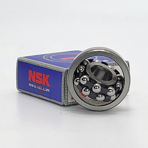
NSK NSK Self-Aligning Ball Bearings, Cylindrical Bore Bearings 2320 ,D=100
NSK Self-Aligning Ball Bearings, Cylindrical Bore Bearings 2320 ,D=100 Bearing Numbers Boundary Dimensions (mm) Basic Load Ratings (kN) Limiting Speeds (min-1) Constant e Axial Load Factors Mass (kg) approx. d D B r min. Cr C0r Grease Oil Y2 Y3 Y0 2320 100 215 73 3 187 79 2400 3200 0.38 2.6 1.7 1.8 11.4 DESIGN, TYPES, AND FEATURESThe outer ring of a self-aligning ball bearing has a spherical raceway and its center of curvature coincides with that of the bearing; therefore, the axis of the inner ring, balls and cage can deflect to some extent around the bearing center. This type is recommended when the alignment of the shaft and housing is difficult and when the shaft may bend. Since the contact angle is small, axial load capacity is low. Pressed-steel cages are usually used. PROTRUSION AMOUNT Some self-aligning ball bearings have balls that protrude from the side face as shown below. This protrusion amount b1 is listed in the following table. PERMISSIBLE MISALIGNMENT The permissible misalignment of self-aligning ball bearings is approximately 0.07 to 0.12 radian (4° to 7°) under normal loads. However, depending on the surrounding structure, such an angle may not be possible. Take care in the design of the bearing surroundings.
$1,527.82
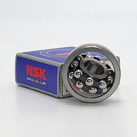
NSK NSK Self-Aligning Ball Bearings, Cylindrical Bore Bearings 2319 ,D=95
NSK Self-Aligning Ball Bearings, Cylindrical Bore Bearings 2319 ,D=95 Bearing Numbers Boundary Dimensions (mm) Basic Load Ratings (kN) Limiting Speeds (min-1) Constant e Axial Load Factors Mass (kg) approx. d D B r min. Cr C0r Grease Oil Y2 Y3 Y0 2319 95 200 67 3 161 64.5 2800 3400 0.38 2.6 1.7 1.8 8.86 DESIGN, TYPES, AND FEATURESThe outer ring of a self-aligning ball bearing has a spherical raceway and its center of curvature coincides with that of the bearing; therefore, the axis of the inner ring, balls and cage can deflect to some extent around the bearing center. This type is recommended when the alignment of the shaft and housing is difficult and when the shaft may bend. Since the contact angle is small, axial load capacity is low. Pressed-steel cages are usually used. PROTRUSION AMOUNT Some self-aligning ball bearings have balls that protrude from the side face as shown below. This protrusion amount b1 is listed in the following table. PERMISSIBLE MISALIGNMENT The permissible misalignment of self-aligning ball bearings is approximately 0.07 to 0.12 radian (4° to 7°) under normal loads. However, depending on the surrounding structure, such an angle may not be possible. Take care in the design of the bearing surroundings.
$1,147.60
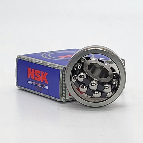
NSK NSK Self-Aligning Ball Bearings, Cylindrical Bore Bearings 2318 ,D=90
NSK Self-Aligning Ball Bearings, Cylindrical Bore Bearings 2318 ,D=90 Bearing Numbers Boundary Dimensions (mm) Basic Load Ratings (kN) Limiting Speeds (min-1) Constant e Axial Load Factors Mass (kg) approx. d D B r min. Cr C0r Grease Oil Y2 Y3 Y0 2318 90 190 64 3 154 57.5 2800 3600 0.38 2.6 1.7 1.7 7.62 DESIGN, TYPES, AND FEATURESThe outer ring of a self-aligning ball bearing has a spherical raceway and its center of curvature coincides with that of the bearing; therefore, the axis of the inner ring, balls and cage can deflect to some extent around the bearing center. This type is recommended when the alignment of the shaft and housing is difficult and when the shaft may bend. Since the contact angle is small, axial load capacity is low. Pressed-steel cages are usually used. PROTRUSION AMOUNT Some self-aligning ball bearings have balls that protrude from the side face as shown below. This protrusion amount b1 is listed in the following table. PERMISSIBLE MISALIGNMENT The permissible misalignment of self-aligning ball bearings is approximately 0.07 to 0.12 radian (4° to 7°) under normal loads. However, depending on the surrounding structure, such an angle may not be possible. Take care in the design of the bearing surroundings.
$961.68
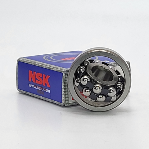
NSK NSK Self-Aligning Ball Bearings, Cylindrical Bore Bearings 2317 ,D=85
NSK Self-Aligning Ball Bearings, Cylindrical Bore Bearings 2317 ,D=85 Bearing Numbers Boundary Dimensions (mm) Basic Load Ratings (kN) Limiting Speeds (min-1) Constant e Axial Load Factors Mass (kg) approx. d D B r min. Cr C0r Grease Oil Y2 Y3 Y0 2317 85 180 60 3 142 51.5 3000 3800 0.37 2.6 1.7 1.8 6.43 DESIGN, TYPES, AND FEATURESThe outer ring of a self-aligning ball bearing has a spherical raceway and its center of curvature coincides with that of the bearing; therefore, the axis of the inner ring, balls and cage can deflect to some extent around the bearing center. This type is recommended when the alignment of the shaft and housing is difficult and when the shaft may bend. Since the contact angle is small, axial load capacity is low. Pressed-steel cages are usually used. PROTRUSION AMOUNT Some self-aligning ball bearings have balls that protrude from the side face as shown below. This protrusion amount b1 is listed in the following table. PERMISSIBLE MISALIGNMENT The permissible misalignment of self-aligning ball bearings is approximately 0.07 to 0.12 radian (4° to 7°) under normal loads. However, depending on the surrounding structure, such an angle may not be possible. Take care in the design of the bearing surroundings.
$702.30
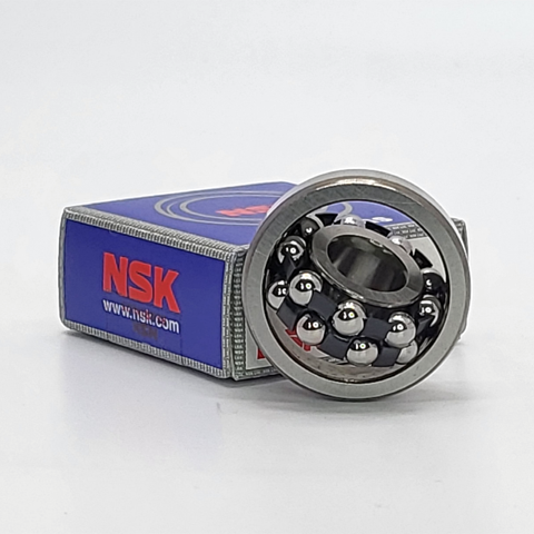
NSK NSK Self-Aligning Ball Bearings, Cylindrical Bore Bearings 2316 ,D=80
NSK Self-Aligning Ball Bearings, Cylindrical Bore Bearings 2316 ,D=80 Bearing Numbers Boundary Dimensions (mm) Basic Load Ratings (kN) Limiting Speeds (min-1) Constant e Axial Load Factors Mass (kg) approx. d D B r min. Cr C0r Grease Oil Y2 Y3 Y0 2316 80 170 58 2.1 130 45 3200 4000 0.39 2.5 1.6 1.7 5.44 DESIGN, TYPES, AND FEATURESThe outer ring of a self-aligning ball bearing has a spherical raceway and its center of curvature coincides with that of the bearing; therefore, the axis of the inner ring, balls and cage can deflect to some extent around the bearing center. This type is recommended when the alignment of the shaft and housing is difficult and when the shaft may bend. Since the contact angle is small, axial load capacity is low. Pressed-steel cages are usually used. PROTRUSION AMOUNT Some self-aligning ball bearings have balls that protrude from the side face as shown below. This protrusion amount b1 is listed in the following table. PERMISSIBLE MISALIGNMENT The permissible misalignment of self-aligning ball bearings is approximately 0.07 to 0.12 radian (4° to 7°) under normal loads. However, depending on the surrounding structure, such an angle may not be possible. Take care in the design of the bearing surroundings.
$488.44
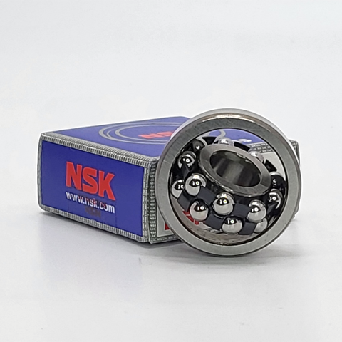
NSK NSK Self-Aligning Ball Bearings, Cylindrical Bore Bearings 2315 ,D=75
NSK Self-Aligning Ball Bearings, Cylindrical Bore Bearings 2315 ,D=75 Bearing Numbers Boundary Dimensions (mm) Basic Load Ratings (kN) Limiting Speeds (min-1) Constant e Axial Load Factors Mass (kg) approx. d D B r min. Cr C0r Grease Oil Y2 Y3 Y0 2315 75 160 55 2.1 125 43 3400 4300 0.38 2.5 1.6 1.7 4.67 DESIGN, TYPES, AND FEATURESThe outer ring of a self-aligning ball bearing has a spherical raceway and its center of curvature coincides with that of the bearing; therefore, the axis of the inner ring, balls and cage can deflect to some extent around the bearing center. This type is recommended when the alignment of the shaft and housing is difficult and when the shaft may bend. Since the contact angle is small, axial load capacity is low. Pressed-steel cages are usually used. PROTRUSION AMOUNT Some self-aligning ball bearings have balls that protrude from the side face as shown below. This protrusion amount b1 is listed in the following table. PERMISSIBLE MISALIGNMENT The permissible misalignment of self-aligning ball bearings is approximately 0.07 to 0.12 radian (4° to 7°) under normal loads. However, depending on the surrounding structure, such an angle may not be possible. Take care in the design of the bearing surroundings.
$478.00
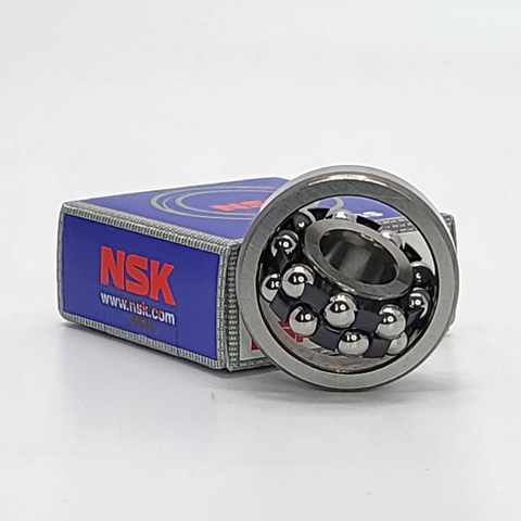
NSK NSK Self-Aligning Ball Bearings, Cylindrical Bore Bearings 2314 ,D=70
NSK Self-Aligning Ball Bearings, Cylindrical Bore Bearings 2314 ,D=70 Bearing Numbers Boundary Dimensions (mm) Basic Load Ratings (kN) Limiting Speeds (min-1) Constant e Axial Load Factors Mass (kg) approx. d D B r min. Cr C0r Grease Oil Y2 Y3 Y0 2314 70 150 51 2.1 111 37.5 3600 4500 0.38 2.6 1.7 1.8 3.8 DESIGN, TYPES, AND FEATURESThe outer ring of a self-aligning ball bearing has a spherical raceway and its center of curvature coincides with that of the bearing; therefore, the axis of the inner ring, balls and cage can deflect to some extent around the bearing center. This type is recommended when the alignment of the shaft and housing is difficult and when the shaft may bend. Since the contact angle is small, axial load capacity is low. Pressed-steel cages are usually used. PROTRUSION AMOUNT Some self-aligning ball bearings have balls that protrude from the side face as shown below. This protrusion amount b1 is listed in the following table. PERMISSIBLE MISALIGNMENT The permissible misalignment of self-aligning ball bearings is approximately 0.07 to 0.12 radian (4° to 7°) under normal loads. However, depending on the surrounding structure, such an angle may not be possible. Take care in the design of the bearing surroundings.
$362.84
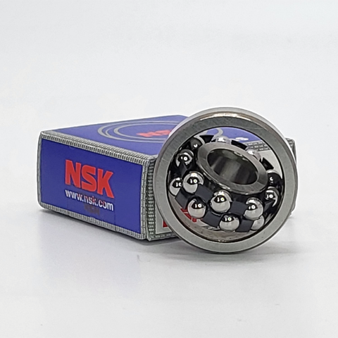
NSK NSK Self-Aligning Ball Bearings, Cylindrical Bore Bearings 2313 ,D=65
NSK Self-Aligning Ball Bearings, Cylindrical Bore Bearings 2313 ,D=65 Bearing Numbers Boundary Dimensions (mm) Basic Load Ratings (kN) Limiting Speeds (min-1) Constant e Axial Load Factors Mass (kg) approx. d D B r min. Cr C0r Grease Oil Y2 Y3 Y0 2313 65 140 48 2.1 97 32.5 3800 4800 0.39 2.5 1.6 1.7 3.11 DESIGN, TYPES, AND FEATURESThe outer ring of a self-aligning ball bearing has a spherical raceway and its center of curvature coincides with that of the bearing; therefore, the axis of the inner ring, balls and cage can deflect to some extent around the bearing center. This type is recommended when the alignment of the shaft and housing is difficult and when the shaft may bend. Since the contact angle is small, axial load capacity is low. Pressed-steel cages are usually used. PROTRUSION AMOUNT Some self-aligning ball bearings have balls that protrude from the side face as shown below. This protrusion amount b1 is listed in the following table. PERMISSIBLE MISALIGNMENT The permissible misalignment of self-aligning ball bearings is approximately 0.07 to 0.12 radian (4° to 7°) under normal loads. However, depending on the surrounding structure, such an angle may not be possible. Take care in the design of the bearing surroundings.
$248.58
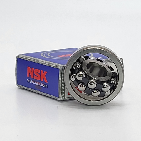
NSK NSK Self-Aligning Ball Bearings, Cylindrical Bore Bearings 2312 ,D=60
NSK Self-Aligning Ball Bearings, Cylindrical Bore Bearings 2312 ,D=60 Bearing Numbers Boundary Dimensions (mm) Basic Load Ratings (kN) Limiting Speeds (min-1) Constant e Axial Load Factors Mass (kg) approx. d D B r min. Cr C0r Grease Oil Y2 Y3 Y0 2312 60 130 46 2.1 88.5 28.3 4300 5300 0.4 2.4 1.6 1.6 2.49 DESIGN, TYPES, AND FEATURESThe outer ring of a self-aligning ball bearing has a spherical raceway and its center of curvature coincides with that of the bearing; therefore, the axis of the inner ring, balls and cage can deflect to some extent around the bearing center. This type is recommended when the alignment of the shaft and housing is difficult and when the shaft may bend. Since the contact angle is small, axial load capacity is low. Pressed-steel cages are usually used. PROTRUSION AMOUNT Some self-aligning ball bearings have balls that protrude from the side face as shown below. This protrusion amount b1 is listed in the following table. PERMISSIBLE MISALIGNMENT The permissible misalignment of self-aligning ball bearings is approximately 0.07 to 0.12 radian (4° to 7°) under normal loads. However, depending on the surrounding structure, such an angle may not be possible. Take care in the design of the bearing surroundings.
$202.06
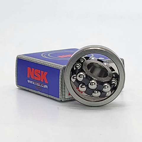
NSK NSK Self-Aligning Ball Bearings, Cylindrical Bore Bearings 2311 ,D=55
NSK Self-Aligning Ball Bearings, Cylindrical Bore Bearings 2311 ,D=55 Bearing Numbers Boundary Dimensions (mm) Basic Load Ratings (kN) Limiting Speeds (min-1) Constant e Axial Load Factors Mass (kg) approx. d D B r min. Cr C0r Grease Oil Y2 Y3 Y0 2311 55 120 43 2 76.5 24 4800 6000 0.41 2.4 1.5 1.6 2.03 DESIGN, TYPES, AND FEATURESThe outer ring of a self-aligning ball bearing has a spherical raceway and its center of curvature coincides with that of the bearing; therefore, the axis of the inner ring, balls and cage can deflect to some extent around the bearing center. This type is recommended when the alignment of the shaft and housing is difficult and when the shaft may bend. Since the contact angle is small, axial load capacity is low. Pressed-steel cages are usually used. PROTRUSION AMOUNT Some self-aligning ball bearings have balls that protrude from the side face as shown below. This protrusion amount b1 is listed in the following table. PERMISSIBLE MISALIGNMENT The permissible misalignment of self-aligning ball bearings is approximately 0.07 to 0.12 radian (4° to 7°) under normal loads. However, depending on the surrounding structure, such an angle may not be possible. Take care in the design of the bearing surroundings.
$165.98
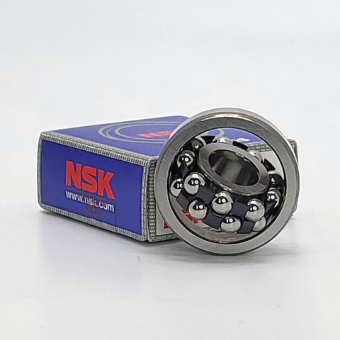
NSK NSK Self-Aligning Ball Bearings, Cylindrical Bore Bearings 2310 ,D=50
NSK Self-Aligning Ball Bearings, Cylindrical Bore Bearings 2310 ,D=50 Bearing Numbers Boundary Dimensions (mm) Basic Load Ratings (kN) Limiting Speeds (min-1) Constant e Axial Load Factors Mass (kg) approx. d D B r min. Cr C0r Grease Oil Y2 Y3 Y0 2310 50 110 40 2 65 20.2 5000 6300 0.42 2.3 1.5 1.6 1.58 DESIGN, TYPES, AND FEATURESThe outer ring of a self-aligning ball bearing has a spherical raceway and its center of curvature coincides with that of the bearing; therefore, the axis of the inner ring, balls and cage can deflect to some extent around the bearing center. This type is recommended when the alignment of the shaft and housing is difficult and when the shaft may bend. Since the contact angle is small, axial load capacity is low. Pressed-steel cages are usually used. PROTRUSION AMOUNT Some self-aligning ball bearings have balls that protrude from the side face as shown below. This protrusion amount b1 is listed in the following table. PERMISSIBLE MISALIGNMENT The permissible misalignment of self-aligning ball bearings is approximately 0.07 to 0.12 radian (4° to 7°) under normal loads. However, depending on the surrounding structure, such an angle may not be possible. Take care in the design of the bearing surroundings.
$121.16
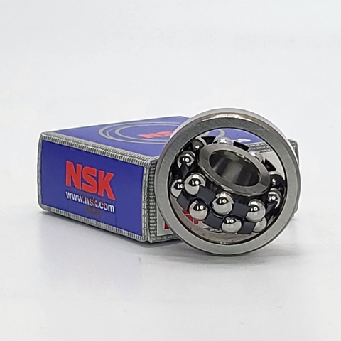
NSK NSK Self-Aligning Ball Bearings, Cylindrical Bore Bearings 2309 ,D=45
NSK Self-Aligning Ball Bearings, Cylindrical Bore Bearings 2309 ,D=45 Bearing Numbers Boundary Dimensions (mm) Basic Load Ratings (kN) Limiting Speeds (min-1) Constant e Axial Load Factors Mass (kg) approx. d D B r min. Cr C0r Grease Oil Y2 Y3 Y0 2309 45 100 36 1.5 55 16.7 5600 7100 0.41 2.4 1.5 1.6 1.2 DESIGN, TYPES, AND FEATURESThe outer ring of a self-aligning ball bearing has a spherical raceway and its center of curvature coincides with that of the bearing; therefore, the axis of the inner ring, balls and cage can deflect to some extent around the bearing center. This type is recommended when the alignment of the shaft and housing is difficult and when the shaft may bend. Since the contact angle is small, axial load capacity is low. Pressed-steel cages are usually used. PROTRUSION AMOUNT Some self-aligning ball bearings have balls that protrude from the side face as shown below. This protrusion amount b1 is listed in the following table. PERMISSIBLE MISALIGNMENT The permissible misalignment of self-aligning ball bearings is approximately 0.07 to 0.12 radian (4° to 7°) under normal loads. However, depending on the surrounding structure, such an angle may not be possible. Take care in the design of the bearing surroundings.
$102.80
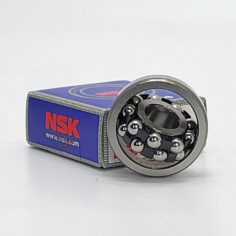
NSK NSK Self-Aligning Ball Bearings, Cylindrical Bore Bearings 2308 ,D=40
NSK Self-Aligning Ball Bearings, Cylindrical Bore Bearings 2308 ,D=40 Bearing Numbers Boundary Dimensions (mm) Basic Load Ratings (kN) Limiting Speeds (min-1) Constant e Axial Load Factors Mass (kg) approx. d D B r min. Cr C0r Grease Oil Y2 Y3 Y0 2308 40 90 33 1.5 45.5 13.5 6300 8000 0.43 2.3 1.5 1.5 0.889 DESIGN, TYPES, AND FEATURESThe outer ring of a self-aligning ball bearing has a spherical raceway and its center of curvature coincides with that of the bearing; therefore, the axis of the inner ring, balls and cage can deflect to some extent around the bearing center. This type is recommended when the alignment of the shaft and housing is difficult and when the shaft may bend. Since the contact angle is small, axial load capacity is low. Pressed-steel cages are usually used. PROTRUSION AMOUNT Some self-aligning ball bearings have balls that protrude from the side face as shown below. This protrusion amount b1 is listed in the following table. PERMISSIBLE MISALIGNMENT The permissible misalignment of self-aligning ball bearings is approximately 0.07 to 0.12 radian (4° to 7°) under normal loads. However, depending on the surrounding structure, such an angle may not be possible. Take care in the design of the bearing surroundings.
$79.18
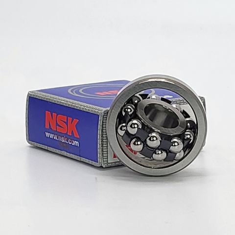
NSK NSK Self-Aligning Ball Bearings, Cylindrical Bore Bearings 2307 ,D=35
NSK Self-Aligning Ball Bearings, Cylindrical Bore Bearings 2307 ,D=35 Bearing Numbers Boundary Dimensions (mm) Basic Load Ratings (kN) Limiting Speeds (min-1) Constant e Axial Load Factors Mass (kg) approx. d D B r min. Cr C0r Grease Oil Y2 Y3 Y0 2307 35 80 31 1.5 40 11.3 7100 9000 0.46 2.1 1.4 1.4 0.642 DESIGN, TYPES, AND FEATURESThe outer ring of a self-aligning ball bearing has a spherical raceway and its center of curvature coincides with that of the bearing; therefore, the axis of the inner ring, balls and cage can deflect to some extent around the bearing center. This type is recommended when the alignment of the shaft and housing is difficult and when the shaft may bend. Since the contact angle is small, axial load capacity is low. Pressed-steel cages are usually used. PROTRUSION AMOUNT Some self-aligning ball bearings have balls that protrude from the side face as shown below. This protrusion amount b1 is listed in the following table. PERMISSIBLE MISALIGNMENT The permissible misalignment of self-aligning ball bearings is approximately 0.07 to 0.12 radian (4° to 7°) under normal loads. However, depending on the surrounding structure, such an angle may not be possible. Take care in the design of the bearing surroundings.
$68.08
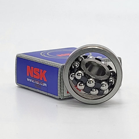
NSK NSK Self-Aligning Ball Bearings, Cylindrical Bore Bearings 2306 ,D=30
NSK Self-Aligning Ball Bearings, Cylindrical Bore Bearings 2306 ,D=30 Bearing Numbers Boundary Dimensions (mm) Basic Load Ratings (kN) Limiting Speeds (min-1) Constant e Axial Load Factors Mass (kg) approx. d D B r min. Cr C0r Grease Oil Y2 Y3 Y0 2306 30 72 27 1.1 32 8.75 8000 10000 0.44 2.2 1.4 1.5 0.48 DESIGN, TYPES, AND FEATURESThe outer ring of a self-aligning ball bearing has a spherical raceway and its center of curvature coincides with that of the bearing; therefore, the axis of the inner ring, balls and cage can deflect to some extent around the bearing center. This type is recommended when the alignment of the shaft and housing is difficult and when the shaft may bend. Since the contact angle is small, axial load capacity is low. Pressed-steel cages are usually used. PROTRUSION AMOUNT Some self-aligning ball bearings have balls that protrude from the side face as shown below. This protrusion amount b1 is listed in the following table. PERMISSIBLE MISALIGNMENT The permissible misalignment of self-aligning ball bearings is approximately 0.07 to 0.12 radian (4° to 7°) under normal loads. However, depending on the surrounding structure, such an angle may not be possible. Take care in the design of the bearing surroundings.
$52.74
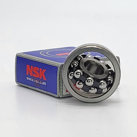
NSK NSK Self-Aligning Ball Bearings, Cylindrical Bore Bearings 2305 ,D=25
NSK Self-Aligning Ball Bearings, Cylindrical Bore Bearings 2305 ,D=25 Bearing Numbers Boundary Dimensions (mm) Basic Load Ratings (kN) Limiting Speeds (min-1) Constant e Axial Load Factors Mass (kg) approx. d D B r min. Cr C0r Grease Oil Y2 Y3 Y0 2305 25 62 24 1.1 24.9 6.6 9500 12000 0.46 2.1 1.4 1.4 0.319 DESIGN, TYPES, AND FEATURESThe outer ring of a self-aligning ball bearing has a spherical raceway and its center of curvature coincides with that of the bearing; therefore, the axis of the inner ring, balls and cage can deflect to some extent around the bearing center. This type is recommended when the alignment of the shaft and housing is difficult and when the shaft may bend. Since the contact angle is small, axial load capacity is low. Pressed-steel cages are usually used. PROTRUSION AMOUNT Some self-aligning ball bearings have balls that protrude from the side face as shown below. This protrusion amount b1 is listed in the following table. PERMISSIBLE MISALIGNMENT The permissible misalignment of self-aligning ball bearings is approximately 0.07 to 0.12 radian (4° to 7°) under normal loads. However, depending on the surrounding structure, such an angle may not be possible. Take care in the design of the bearing surroundings.
$43.58
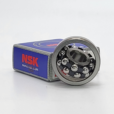
NSK NSK Self-Aligning Ball Bearings, Cylindrical Bore Bearings 2304 ,D=20
NSK Self-Aligning Ball Bearings, Cylindrical Bore Bearings 2304 ,D=20 Bearing Numbers Boundary Dimensions (mm) Basic Load Ratings (kN) Limiting Speeds (min-1) Constant e Axial Load Factors Mass (kg) approx. d D B r min. Cr C0r Grease Oil Y2 Y3 Y0 2304 20 52 21 1.1 18.5 4.7 11000 14000 0.5 1.9 1.2 1.3 0.193 DESIGN, TYPES, AND FEATURESThe outer ring of a self-aligning ball bearing has a spherical raceway and its center of curvature coincides with that of the bearing; therefore, the axis of the inner ring, balls and cage can deflect to some extent around the bearing center. This type is recommended when the alignment of the shaft and housing is difficult and when the shaft may bend. Since the contact angle is small, axial load capacity is low. Pressed-steel cages are usually used. PROTRUSION AMOUNT Some self-aligning ball bearings have balls that protrude from the side face as shown below. This protrusion amount b1 is listed in the following table. PERMISSIBLE MISALIGNMENT The permissible misalignment of self-aligning ball bearings is approximately 0.07 to 0.12 radian (4° to 7°) under normal loads. However, depending on the surrounding structure, such an angle may not be possible. Take care in the design of the bearing surroundings.
$32.30
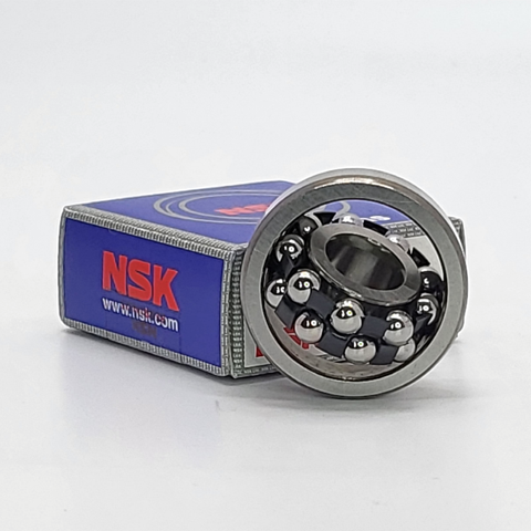
NSK NSK Self-Aligning Ball Bearings, Cylindrical Bore Bearings 2303 ,D=17
NSK Self-Aligning Ball Bearings, Cylindrical Bore Bearings 2303 ,D=17 Bearing Numbers Boundary Dimensions (mm) Basic Load Ratings (kN) Limiting Speeds (min-1) Constant e Axial Load Factors Mass (kg) approx. d D B r min. Cr C0r Grease Oil Y2 Y3 Y0 2303 17 47 19 1 14.7 3.55 13000 16000 0.51 1.9 1.2 1.3 0.15 DESIGN, TYPES, AND FEATURESThe outer ring of a self-aligning ball bearing has a spherical raceway and its center of curvature coincides with that of the bearing; therefore, the axis of the inner ring, balls and cage can deflect to some extent around the bearing center. This type is recommended when the alignment of the shaft and housing is difficult and when the shaft may bend. Since the contact angle is small, axial load capacity is low. Pressed-steel cages are usually used. PROTRUSION AMOUNT Some self-aligning ball bearings have balls that protrude from the side face as shown below. This protrusion amount b1 is listed in the following table. PERMISSIBLE MISALIGNMENT The permissible misalignment of self-aligning ball bearings is approximately 0.07 to 0.12 radian (4° to 7°) under normal loads. However, depending on the surrounding structure, such an angle may not be possible. Take care in the design of the bearing surroundings.
$26.90
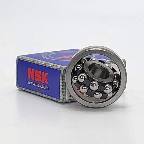
NSK NSK Self-Aligning Ball Bearings, Cylindrical Bore Bearings 2302 ,D=15
NSK Self-Aligning Ball Bearings, Cylindrical Bore Bearings 2302 ,D=15 Bearing Numbers Boundary Dimensions (mm) Basic Load Ratings (kN) Limiting Speeds (min-1) Constant e Axial Load Factors Mass (kg) approx. d D B r min. Cr C0r Grease Oil Y2 Y3 Y0 2302 15 42 17 1 12.3 2.91 14000 18000 0.51 1.9 1.2 1.3 0.108 DESIGN, TYPES, AND FEATURESThe outer ring of a self-aligning ball bearing has a spherical raceway and its center of curvature coincides with that of the bearing; therefore, the axis of the inner ring, balls and cage can deflect to some extent around the bearing center. This type is recommended when the alignment of the shaft and housing is difficult and when the shaft may bend. Since the contact angle is small, axial load capacity is low. Pressed-steel cages are usually used. PROTRUSION AMOUNT Some self-aligning ball bearings have balls that protrude from the side face as shown below. This protrusion amount b1 is listed in the following table. PERMISSIBLE MISALIGNMENT The permissible misalignment of self-aligning ball bearings is approximately 0.07 to 0.12 radian (4° to 7°) under normal loads. However, depending on the surrounding structure, such an angle may not be possible. Take care in the design of the bearing surroundings.
$24.12
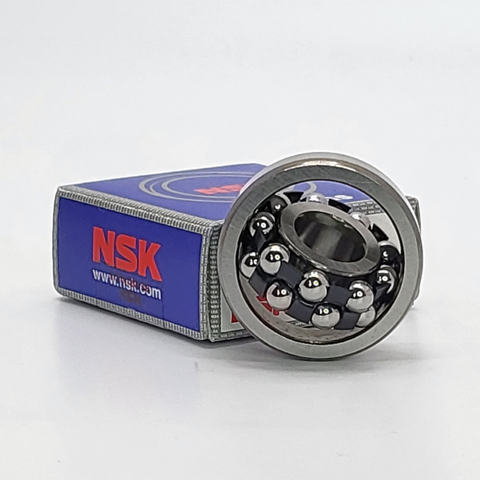
NSK NSK Self-Aligning Ball Bearings, Cylindrical Bore Bearings 2301 ,D=12
NSK Self-Aligning Ball Bearings, Cylindrical Bore Bearings 2301 ,D=12 Bearing Numbers Boundary Dimensions (mm) Basic Load Ratings (kN) Limiting Speeds (min-1) Constant e Axial Load Factors Mass (kg) approx. d D B r min. Cr C0r Grease Oil Y2 Y3 Y0 2301 12 37 17 1 12.1 2.73 17000 22000 0.6 1.6 1.1 1.1 0.082 DESIGN, TYPES, AND FEATURESThe outer ring of a self-aligning ball bearing has a spherical raceway and its center of curvature coincides with that of the bearing; therefore, the axis of the inner ring, balls and cage can deflect to some extent around the bearing center. This type is recommended when the alignment of the shaft and housing is difficult and when the shaft may bend. Since the contact angle is small, axial load capacity is low. Pressed-steel cages are usually used. PROTRUSION AMOUNT Some self-aligning ball bearings have balls that protrude from the side face as shown below. This protrusion amount b1 is listed in the following table. PERMISSIBLE MISALIGNMENT The permissible misalignment of self-aligning ball bearings is approximately 0.07 to 0.12 radian (4° to 7°) under normal loads. However, depending on the surrounding structure, such an angle may not be possible. Take care in the design of the bearing surroundings.
$23.18
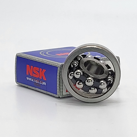
NSK NSK Self-Aligning Ball Bearings, Cylindrical Bore Bearings 2300 ,D=10
NSK Self-Aligning Ball Bearings, Cylindrical Bore Bearings 2300 ,D=10 Bearing Numbers Boundary Dimensions (mm) Basic Load Ratings (kN) Limiting Speeds (min-1) Constant e Axial Load Factors Mass (kg) approx. d D B r min. Cr C0r Grease Oil Y2 Y3 Y0 2300 10 35 17 0.6 9.2 2.01 18000 22000 0.71 1.4 0.89 0.93 0.077 DESIGN, TYPES, AND FEATURESThe outer ring of a self-aligning ball bearing has a spherical raceway and its center of curvature coincides with that of the bearing; therefore, the axis of the inner ring, balls and cage can deflect to some extent around the bearing center. This type is recommended when the alignment of the shaft and housing is difficult and when the shaft may bend. Since the contact angle is small, axial load capacity is low. Pressed-steel cages are usually used. PROTRUSION AMOUNT Some self-aligning ball bearings have balls that protrude from the side face as shown below. This protrusion amount b1 is listed in the following table. PERMISSIBLE MISALIGNMENT The permissible misalignment of self-aligning ball bearings is approximately 0.07 to 0.12 radian (4° to 7°) under normal loads. However, depending on the surrounding structure, such an angle may not be possible. Take care in the design of the bearing surroundings.
$25.00
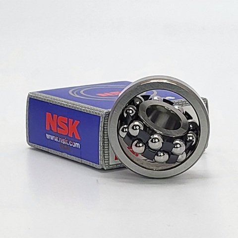
NSK NSK Self-Aligning Ball Bearings, Cylindrical Bore Bearings 2220 ,D=100
NSK Self-Aligning Ball Bearings, Cylindrical Bore Bearings 2220 ,D=100 Bearing Numbers Boundary Dimensions (mm) Basic Load Ratings (kN) Limiting Speeds (min-1) Constant e Axial Load Factors Mass (kg) approx. d D B r min. Cr C0r Grease Oil Y2 Y3 Y0 2220 100 180 46 2.1 94.5 38.5 3200 3800 0.27 3.7 2.4 2.5 4.51 DESIGN, TYPES, AND FEATURESThe outer ring of a self-aligning ball bearing has a spherical raceway and its center of curvature coincides with that of the bearing; therefore, the axis of the inner ring, balls and cage can deflect to some extent around the bearing center. This type is recommended when the alignment of the shaft and housing is difficult and when the shaft may bend. Since the contact angle is small, axial load capacity is low. Pressed-steel cages are usually used. PROTRUSION AMOUNT Some self-aligning ball bearings have balls that protrude from the side face as shown below. This protrusion amount b1 is listed in the following table. PERMISSIBLE MISALIGNMENT The permissible misalignment of self-aligning ball bearings is approximately 0.07 to 0.12 radian (4° to 7°) under normal loads. However, depending on the surrounding structure, such an angle may not be possible. Take care in the design of the bearing surroundings.
$450.70
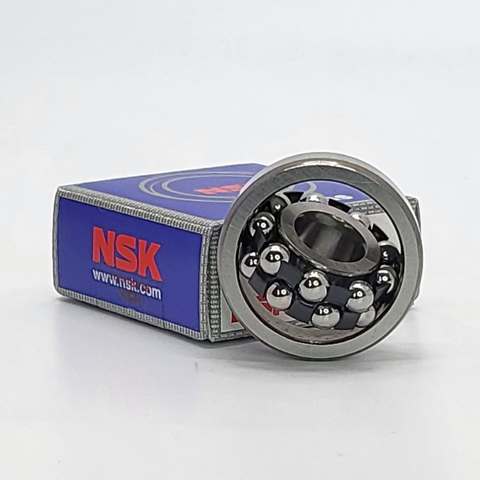
NSK NSK Self-Aligning Ball Bearings, Cylindrical Bore Bearings 2219 ,D=95
NSK Self-Aligning Ball Bearings, Cylindrical Bore Bearings 2219 ,D=95 Bearing Numbers Boundary Dimensions (mm) Basic Load Ratings (kN) Limiting Speeds (min-1) Constant e Axial Load Factors Mass (kg) approx. d D B r min. Cr C0r Grease Oil Y2 Y3 Y0 2219 95 170 43 2.1 84 34.5 3400 4000 0.27 3.7 2.4 2.5 3.76 DESIGN, TYPES, AND FEATURESThe outer ring of a self-aligning ball bearing has a spherical raceway and its center of curvature coincides with that of the bearing; therefore, the axis of the inner ring, balls and cage can deflect to some extent around the bearing center. This type is recommended when the alignment of the shaft and housing is difficult and when the shaft may bend. Since the contact angle is small, axial load capacity is low. Pressed-steel cages are usually used. PROTRUSION AMOUNT Some self-aligning ball bearings have balls that protrude from the side face as shown below. This protrusion amount b1 is listed in the following table. PERMISSIBLE MISALIGNMENT The permissible misalignment of self-aligning ball bearings is approximately 0.07 to 0.12 radian (4° to 7°) under normal loads. However, depending on the surrounding structure, such an angle may not be possible. Take care in the design of the bearing surroundings.
$423.38
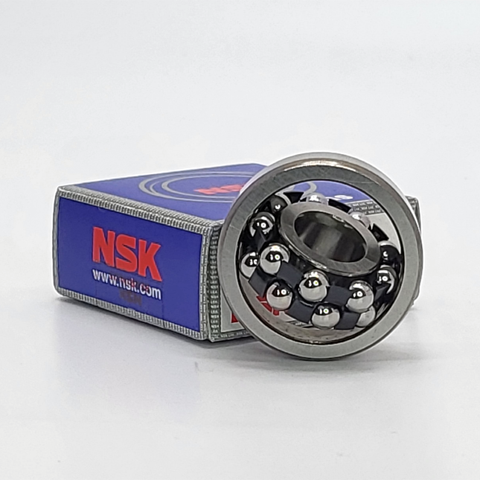
NSK NSK Self-Aligning Ball Bearings, Cylindrical Bore Bearings 2218 ,D=90
NSK Self-Aligning Ball Bearings, Cylindrical Bore Bearings 2218 ,D=90 Bearing Numbers Boundary Dimensions (mm) Basic Load Ratings (kN) Limiting Speeds (min-1) Constant e Axial Load Factors Mass (kg) approx. d D B r min. Cr C0r Grease Oil Y2 Y3 Y0 2218 90 160 40 2 70.5 28.7 3600 4300 0.27 3.7 2.4 2.5 3.09 DESIGN, TYPES, AND FEATURESThe outer ring of a self-aligning ball bearing has a spherical raceway and its center of curvature coincides with that of the bearing; therefore, the axis of the inner ring, balls and cage can deflect to some extent around the bearing center. This type is recommended when the alignment of the shaft and housing is difficult and when the shaft may bend. Since the contact angle is small, axial load capacity is low. Pressed-steel cages are usually used. PROTRUSION AMOUNT Some self-aligning ball bearings have balls that protrude from the side face as shown below. This protrusion amount b1 is listed in the following table. PERMISSIBLE MISALIGNMENT The permissible misalignment of self-aligning ball bearings is approximately 0.07 to 0.12 radian (4° to 7°) under normal loads. However, depending on the surrounding structure, such an angle may not be possible. Take care in the design of the bearing surroundings.
$312.84


