Products

NSK NSK Angular Contact Ball Bearings ,A :Contact Angle of 30°, 7316AW ,D=80
NSK Angular Contact Ball Bearings ,A :Contact Angle of 30°, 7316AW ,D=80 Bearing Numbers Boundary Dimensions (mm) Basic Load Ratings (kN) Limiting Speeds (min-1) Factor f0 Mass (kg) approx. d D B r min. r1 min. Cr C0r Grease Oil 7316AW 80 170 39 2.1 1.1 147 119 2800 3800 ?€ 3.71 DESIGN, TYPES, AND FEATURES SINGLE-ROW ANGULAR CONTACT BALL BEARINGS Single-row angular contact ball bearings have a contact angle allowing them to sustain significant axial loads in one direction together with radial loads. Because of their design, when a radial load is applied, an axial force component is produced; therefore, two or more opposed bearings must be used. Since the rigidity of single-row angular contact ball bearings can be increased by preloading, they are often used in the main spindles of machine tools where high running accuracy is required (refer to Chapter 9 Preload on Page A192 for more information). Usually, the cages for angular contact ball bearings with a contact angle of 30° (designation A) or 40°(designation B) are made in accordance with Table 1, but depending on the application, machined synthetic-resin cages or molded polyamide-resin cages may also be used. The basic load ratings given in the bearing tables are based on standard cages. Though the figures in the bearing tables on Pages C086 to C101 for bearing bore diameters of 10 to 120 show bearings with single-shoulder inner rings, dual-shoulder bearings are also available. Please consult NSK for more detailed information. MATCHED ANGULAR CONTACT BALL BEARINGS The types and features of matched angular contact ball bearings are shown in Table 2. Table 2 Types and Features of Matched Angular Contact Ball Bearings Figure Arrangement Features Back-to-Back(DB)(Example)7208 A DB Radial loads and axial loads in both directions can be sustained. Since the distance between the effective load centers a0 is large, this type is suitable if moments are applied. Face-to-Face(DF)(Example)7208 B DF Radial loads and axial loads in both directions can be sustained. Compared with the DB Type, the distance between the effective load centers is small, so the capacity to sustain moments is inferior. Tandem(DT)(Example)7208 A DT Radial loads and axial loads in one direction can be sustained. Since two bearings share the axial load, this arrangement is used when the load in one direction is heavy. ?¡Formulation of Bearing Designations Single-Row Matched Angular Contact Ball Bearings ? Bearing type 7 : Single-row angular contact ball bearings, matched angular contact ball bearings ?¡Dimension Series 2 : 02 Series, 3 : 03 Series, 9 : 19 Series, 0 : 10 Series ?¢Bore number Less than 03, Bearing bore 00 : 10mm, 01 : 12mm, 02 : 15mm, 03 : 17mmOver 04, Bearing bore Bore number ×5 (mm) ?£Contact angle C : 15°, A5 : 25°, A : 30°, B : 40° ?¤Internal design EA : High Load Capacity ?¥Cage W : Pressed steel Cage, T85 : Machined brass cage (ball-guided),No designation : Machined brass cage (inner ring guided), TYN : Polyamide resin cage,T85 : Polyamide 46 resin cage, T7 : L-PPS resin cage ?¦Arrangement SU: Universal arrangement (single-row), DU : Universal arrangement (double-row),DB : Back-to-back arrangement, DF : Face-to-face arrangement, DT : Tandem arrangement ?§Preload / Axial internal clearance EL : Extra light preload, L : Light preload, M : Medium preload, H : Heavy preloadOmitted : CN clearance, C3 : Clearance greater than CN, C4 : Clearance greater than C3,CNB : CN Clearance equivalent (universal arrangement) DOUBLE-ROW ANGULAR CONTACT BALL BEARINGS Double-row angular contact ball bearings are essentially a back- to-back mounting of two single-row angular contact ball bearings, but their inner and outer rings are each integrated into one. These bearings can sustain axial loads in both directions and offer good capacity for sustaining moment loads. They are often used as fixed- end bearings and contain cages made of pressed steel. ?¡Formulation of Bearing Designations Double-Row Angular Contact Ball Bearings ? Bearing type 5 : Double-row angular contact ball bearings ?¡Dimension Series 2 : 02 Series 3: 03 Series ?¢Bore number 03 and under: 00 : 10mm, 01 : 12mm, 02 : 15mm, 03 : 17mm 04 and over: Bore diameter bore number ×5 (mm) ?£Internal design ZZ: Steel shield on both sides, DDU: Rubber contact seal on both sides VV: Rubber noncontact seal on both sides ?¤Seals/shields Z: Steel shield on one sides, DU: Rubber contact seal on one side, V: Rubber non-contact seal on one side ?¥Grease* NS7: NS HI-LUBE
$231.00

NSK NSK Angular Contact Ball Bearings ,A :Contact Angle of 30°, 7317AW ,D=85
NSK Angular Contact Ball Bearings ,A :Contact Angle of 30°, 7317AW ,D=85 Bearing Numbers Boundary Dimensions (mm) Basic Load Ratings (kN) Limiting Speeds (min-1) Factor f0 Mass (kg) approx. d D B r min. r1 min. Cr C0r Grease Oil 7317AW 85 180 41 3 1.1 159 133 2600 3600 ?€ 4.33 DESIGN, TYPES, AND FEATURES SINGLE-ROW ANGULAR CONTACT BALL BEARINGS Single-row angular contact ball bearings have a contact angle allowing them to sustain significant axial loads in one direction together with radial loads. Because of their design, when a radial load is applied, an axial force component is produced; therefore, two or more opposed bearings must be used. Since the rigidity of single-row angular contact ball bearings can be increased by preloading, they are often used in the main spindles of machine tools where high running accuracy is required (refer to Chapter 9 Preload on Page A192 for more information). Usually, the cages for angular contact ball bearings with a contact angle of 30° (designation A) or 40°(designation B) are made in accordance with Table 1, but depending on the application, machined synthetic-resin cages or molded polyamide-resin cages may also be used. The basic load ratings given in the bearing tables are based on standard cages. Though the figures in the bearing tables on Pages C086 to C101 for bearing bore diameters of 10 to 120 show bearings with single-shoulder inner rings, dual-shoulder bearings are also available. Please consult NSK for more detailed information. MATCHED ANGULAR CONTACT BALL BEARINGS The types and features of matched angular contact ball bearings are shown in Table 2. Table 2 Types and Features of Matched Angular Contact Ball Bearings Figure Arrangement Features Back-to-Back(DB)(Example)7208 A DB Radial loads and axial loads in both directions can be sustained. Since the distance between the effective load centers a0 is large, this type is suitable if moments are applied. Face-to-Face(DF)(Example)7208 B DF Radial loads and axial loads in both directions can be sustained. Compared with the DB Type, the distance between the effective load centers is small, so the capacity to sustain moments is inferior. Tandem(DT)(Example)7208 A DT Radial loads and axial loads in one direction can be sustained. Since two bearings share the axial load, this arrangement is used when the load in one direction is heavy. ?¡Formulation of Bearing Designations Single-Row Matched Angular Contact Ball Bearings ? Bearing type 7 : Single-row angular contact ball bearings, matched angular contact ball bearings ?¡Dimension Series 2 : 02 Series, 3 : 03 Series, 9 : 19 Series, 0 : 10 Series ?¢Bore number Less than 03, Bearing bore 00 : 10mm, 01 : 12mm, 02 : 15mm, 03 : 17mmOver 04, Bearing bore Bore number ×5 (mm) ?£Contact angle C : 15°, A5 : 25°, A : 30°, B : 40° ?¤Internal design EA : High Load Capacity ?¥Cage W : Pressed steel Cage, T85 : Machined brass cage (ball-guided),No designation : Machined brass cage (inner ring guided), TYN : Polyamide resin cage,T85 : Polyamide 46 resin cage, T7 : L-PPS resin cage ?¦Arrangement SU: Universal arrangement (single-row), DU : Universal arrangement (double-row),DB : Back-to-back arrangement, DF : Face-to-face arrangement, DT : Tandem arrangement ?§Preload / Axial internal clearance EL : Extra light preload, L : Light preload, M : Medium preload, H : Heavy preloadOmitted : CN clearance, C3 : Clearance greater than CN, C4 : Clearance greater than C3,CNB : CN Clearance equivalent (universal arrangement) DOUBLE-ROW ANGULAR CONTACT BALL BEARINGS Double-row angular contact ball bearings are essentially a back- to-back mounting of two single-row angular contact ball bearings, but their inner and outer rings are each integrated into one. These bearings can sustain axial loads in both directions and offer good capacity for sustaining moment loads. They are often used as fixed- end bearings and contain cages made of pressed steel. ?¡Formulation of Bearing Designations Double-Row Angular Contact Ball Bearings ? Bearing type 5 : Double-row angular contact ball bearings ?¡Dimension Series 2 : 02 Series 3: 03 Series ?¢Bore number 03 and under: 00 : 10mm, 01 : 12mm, 02 : 15mm, 03 : 17mm 04 and over: Bore diameter bore number ×5 (mm) ?£Internal design ZZ: Steel shield on both sides, DDU: Rubber contact seal on both sides VV: Rubber noncontact seal on both sides ?¤Seals/shields Z: Steel shield on one sides, DU: Rubber contact seal on one side, V: Rubber non-contact seal on one side ?¥Grease* NS7: NS HI-LUBE
$267.24

NSK NSK Angular Contact Ball Bearings ,A :Contact Angle of 30°, 7318AW ,D=90
NSK Angular Contact Ball Bearings ,A :Contact Angle of 30°, 7318AW ,D=90 Bearing Numbers Boundary Dimensions (mm) Basic Load Ratings (kN) Limiting Speeds (min-1) Factor f0 Mass (kg) approx. d D B r min. r1 min. Cr C0r Grease Oil 7318AW 90 190 43 3 1.1 171 147 2600 3400 ?€ 5.06 DESIGN, TYPES, AND FEATURES SINGLE-ROW ANGULAR CONTACT BALL BEARINGS Single-row angular contact ball bearings have a contact angle allowing them to sustain significant axial loads in one direction together with radial loads. Because of their design, when a radial load is applied, an axial force component is produced; therefore, two or more opposed bearings must be used. Since the rigidity of single-row angular contact ball bearings can be increased by preloading, they are often used in the main spindles of machine tools where high running accuracy is required (refer to Chapter 9 Preload on Page A192 for more information). Usually, the cages for angular contact ball bearings with a contact angle of 30° (designation A) or 40°(designation B) are made in accordance with Table 1, but depending on the application, machined synthetic-resin cages or molded polyamide-resin cages may also be used. The basic load ratings given in the bearing tables are based on standard cages. Though the figures in the bearing tables on Pages C086 to C101 for bearing bore diameters of 10 to 120 show bearings with single-shoulder inner rings, dual-shoulder bearings are also available. Please consult NSK for more detailed information. MATCHED ANGULAR CONTACT BALL BEARINGS The types and features of matched angular contact ball bearings are shown in Table 2. Table 2 Types and Features of Matched Angular Contact Ball Bearings Figure Arrangement Features Back-to-Back(DB)(Example)7208 A DB Radial loads and axial loads in both directions can be sustained. Since the distance between the effective load centers a0 is large, this type is suitable if moments are applied. Face-to-Face(DF)(Example)7208 B DF Radial loads and axial loads in both directions can be sustained. Compared with the DB Type, the distance between the effective load centers is small, so the capacity to sustain moments is inferior. Tandem(DT)(Example)7208 A DT Radial loads and axial loads in one direction can be sustained. Since two bearings share the axial load, this arrangement is used when the load in one direction is heavy. ?¡Formulation of Bearing Designations Single-Row Matched Angular Contact Ball Bearings ? Bearing type 7 : Single-row angular contact ball bearings, matched angular contact ball bearings ?¡Dimension Series 2 : 02 Series, 3 : 03 Series, 9 : 19 Series, 0 : 10 Series ?¢Bore number Less than 03, Bearing bore 00 : 10mm, 01 : 12mm, 02 : 15mm, 03 : 17mmOver 04, Bearing bore Bore number ×5 (mm) ?£Contact angle C : 15°, A5 : 25°, A : 30°, B : 40° ?¤Internal design EA : High Load Capacity ?¥Cage W : Pressed steel Cage, T85 : Machined brass cage (ball-guided),No designation : Machined brass cage (inner ring guided), TYN : Polyamide resin cage,T85 : Polyamide 46 resin cage, T7 : L-PPS resin cage ?¦Arrangement SU: Universal arrangement (single-row), DU : Universal arrangement (double-row),DB : Back-to-back arrangement, DF : Face-to-face arrangement, DT : Tandem arrangement ?§Preload / Axial internal clearance EL : Extra light preload, L : Light preload, M : Medium preload, H : Heavy preloadOmitted : CN clearance, C3 : Clearance greater than CN, C4 : Clearance greater than C3,CNB : CN Clearance equivalent (universal arrangement) DOUBLE-ROW ANGULAR CONTACT BALL BEARINGS Double-row angular contact ball bearings are essentially a back- to-back mounting of two single-row angular contact ball bearings, but their inner and outer rings are each integrated into one. These bearings can sustain axial loads in both directions and offer good capacity for sustaining moment loads. They are often used as fixed- end bearings and contain cages made of pressed steel. ?¡Formulation of Bearing Designations Double-Row Angular Contact Ball Bearings ? Bearing type 5 : Double-row angular contact ball bearings ?¡Dimension Series 2 : 02 Series 3: 03 Series ?¢Bore number 03 and under: 00 : 10mm, 01 : 12mm, 02 : 15mm, 03 : 17mm 04 and over: Bore diameter bore number ×5 (mm) ?£Internal design ZZ: Steel shield on both sides, DDU: Rubber contact seal on both sides VV: Rubber noncontact seal on both sides ?¤Seals/shields Z: Steel shield on one sides, DU: Rubber contact seal on one side, V: Rubber non-contact seal on one side ?¥Grease* NS7: NS HI-LUBE
$377.10

NSK NSK Angular Contact Ball Bearings ,A :Contact Angle of 30°, 7319AW ,D=95
NSK Angular Contact Ball Bearings ,A :Contact Angle of 30°, 7319AW ,D=95 Bearing Numbers Boundary Dimensions (mm) Basic Load Ratings (kN) Limiting Speeds (min-1) Factor f0 Mass (kg) approx. d D B r min. r1 min. Cr C0r Grease Oil 7319AW 95 200 45 3 1.1 183 162 2400 3200 ?€ 5.83 DESIGN, TYPES, AND FEATURES SINGLE-ROW ANGULAR CONTACT BALL BEARINGS Single-row angular contact ball bearings have a contact angle allowing them to sustain significant axial loads in one direction together with radial loads. Because of their design, when a radial load is applied, an axial force component is produced; therefore, two or more opposed bearings must be used. Since the rigidity of single-row angular contact ball bearings can be increased by preloading, they are often used in the main spindles of machine tools where high running accuracy is required (refer to Chapter 9 Preload on Page A192 for more information). Usually, the cages for angular contact ball bearings with a contact angle of 30° (designation A) or 40°(designation B) are made in accordance with Table 1, but depending on the application, machined synthetic-resin cages or molded polyamide-resin cages may also be used. The basic load ratings given in the bearing tables are based on standard cages. Though the figures in the bearing tables on Pages C086 to C101 for bearing bore diameters of 10 to 120 show bearings with single-shoulder inner rings, dual-shoulder bearings are also available. Please consult NSK for more detailed information. MATCHED ANGULAR CONTACT BALL BEARINGS The types and features of matched angular contact ball bearings are shown in Table 2. Table 2 Types and Features of Matched Angular Contact Ball Bearings Figure Arrangement Features Back-to-Back(DB)(Example)7208 A DB Radial loads and axial loads in both directions can be sustained. Since the distance between the effective load centers a0 is large, this type is suitable if moments are applied. Face-to-Face(DF)(Example)7208 B DF Radial loads and axial loads in both directions can be sustained. Compared with the DB Type, the distance between the effective load centers is small, so the capacity to sustain moments is inferior. Tandem(DT)(Example)7208 A DT Radial loads and axial loads in one direction can be sustained. Since two bearings share the axial load, this arrangement is used when the load in one direction is heavy. ?¡Formulation of Bearing Designations Single-Row Matched Angular Contact Ball Bearings ? Bearing type 7 : Single-row angular contact ball bearings, matched angular contact ball bearings ?¡Dimension Series 2 : 02 Series, 3 : 03 Series, 9 : 19 Series, 0 : 10 Series ?¢Bore number Less than 03, Bearing bore 00 : 10mm, 01 : 12mm, 02 : 15mm, 03 : 17mmOver 04, Bearing bore Bore number ×5 (mm) ?£Contact angle C : 15°, A5 : 25°, A : 30°, B : 40° ?¤Internal design EA : High Load Capacity ?¥Cage W : Pressed steel Cage, T85 : Machined brass cage (ball-guided),No designation : Machined brass cage (inner ring guided), TYN : Polyamide resin cage,T85 : Polyamide 46 resin cage, T7 : L-PPS resin cage ?¦Arrangement SU: Universal arrangement (single-row), DU : Universal arrangement (double-row),DB : Back-to-back arrangement, DF : Face-to-face arrangement, DT : Tandem arrangement ?§Preload / Axial internal clearance EL : Extra light preload, L : Light preload, M : Medium preload, H : Heavy preloadOmitted : CN clearance, C3 : Clearance greater than CN, C4 : Clearance greater than C3,CNB : CN Clearance equivalent (universal arrangement) DOUBLE-ROW ANGULAR CONTACT BALL BEARINGS Double-row angular contact ball bearings are essentially a back- to-back mounting of two single-row angular contact ball bearings, but their inner and outer rings are each integrated into one. These bearings can sustain axial loads in both directions and offer good capacity for sustaining moment loads. They are often used as fixed- end bearings and contain cages made of pressed steel. ?¡Formulation of Bearing Designations Double-Row Angular Contact Ball Bearings ? Bearing type 5 : Double-row angular contact ball bearings ?¡Dimension Series 2 : 02 Series 3: 03 Series ?¢Bore number 03 and under: 00 : 10mm, 01 : 12mm, 02 : 15mm, 03 : 17mm 04 and over: Bore diameter bore number ×5 (mm) ?£Internal design ZZ: Steel shield on both sides, DDU: Rubber contact seal on both sides VV: Rubber noncontact seal on both sides ?¤Seals/shields Z: Steel shield on one sides, DU: Rubber contact seal on one side, V: Rubber non-contact seal on one side ?¥Grease* NS7: NS HI-LUBE
$390.77

NSK NSK Angular Contact Ball Bearings ,A :Contact Angle of 30°, 7320AW ,D=100
NSK Angular Contact Ball Bearings ,A :Contact Angle of 30°, 7320AW ,D=100 Bearing Numbers Boundary Dimensions (mm) Basic Load Ratings (kN) Limiting Speeds (min-1) Factor f0 Mass (kg) approx. d D B r min. r1 min. Cr C0r Grease Oil 7320AW 100 215 47 3 1.1 207 193 2200 3000 ?€ 7.29 DESIGN, TYPES, AND FEATURES SINGLE-ROW ANGULAR CONTACT BALL BEARINGS Single-row angular contact ball bearings have a contact angle allowing them to sustain significant axial loads in one direction together with radial loads. Because of their design, when a radial load is applied, an axial force component is produced; therefore, two or more opposed bearings must be used. Since the rigidity of single-row angular contact ball bearings can be increased by preloading, they are often used in the main spindles of machine tools where high running accuracy is required (refer to Chapter 9 Preload on Page A192 for more information). Usually, the cages for angular contact ball bearings with a contact angle of 30° (designation A) or 40°(designation B) are made in accordance with Table 1, but depending on the application, machined synthetic-resin cages or molded polyamide-resin cages may also be used. The basic load ratings given in the bearing tables are based on standard cages. Though the figures in the bearing tables on Pages C086 to C101 for bearing bore diameters of 10 to 120 show bearings with single-shoulder inner rings, dual-shoulder bearings are also available. Please consult NSK for more detailed information. MATCHED ANGULAR CONTACT BALL BEARINGS The types and features of matched angular contact ball bearings are shown in Table 2. Table 2 Types and Features of Matched Angular Contact Ball Bearings Figure Arrangement Features Back-to-Back(DB)(Example)7208 A DB Radial loads and axial loads in both directions can be sustained. Since the distance between the effective load centers a0 is large, this type is suitable if moments are applied. Face-to-Face(DF)(Example)7208 B DF Radial loads and axial loads in both directions can be sustained. Compared with the DB Type, the distance between the effective load centers is small, so the capacity to sustain moments is inferior. Tandem(DT)(Example)7208 A DT Radial loads and axial loads in one direction can be sustained. Since two bearings share the axial load, this arrangement is used when the load in one direction is heavy. ?¡Formulation of Bearing Designations Single-Row Matched Angular Contact Ball Bearings ? Bearing type 7 : Single-row angular contact ball bearings, matched angular contact ball bearings ?¡Dimension Series 2 : 02 Series, 3 : 03 Series, 9 : 19 Series, 0 : 10 Series ?¢Bore number Less than 03, Bearing bore 00 : 10mm, 01 : 12mm, 02 : 15mm, 03 : 17mmOver 04, Bearing bore Bore number ×5 (mm) ?£Contact angle C : 15°, A5 : 25°, A : 30°, B : 40° ?¤Internal design EA : High Load Capacity ?¥Cage W : Pressed steel Cage, T85 : Machined brass cage (ball-guided),No designation : Machined brass cage (inner ring guided), TYN : Polyamide resin cage,T85 : Polyamide 46 resin cage, T7 : L-PPS resin cage ?¦Arrangement SU: Universal arrangement (single-row), DU : Universal arrangement (double-row),DB : Back-to-back arrangement, DF : Face-to-face arrangement, DT : Tandem arrangement ?§Preload / Axial internal clearance EL : Extra light preload, L : Light preload, M : Medium preload, H : Heavy preloadOmitted : CN clearance, C3 : Clearance greater than CN, C4 : Clearance greater than C3,CNB : CN Clearance equivalent (universal arrangement) DOUBLE-ROW ANGULAR CONTACT BALL BEARINGS Double-row angular contact ball bearings are essentially a back- to-back mounting of two single-row angular contact ball bearings, but their inner and outer rings are each integrated into one. These bearings can sustain axial loads in both directions and offer good capacity for sustaining moment loads. They are often used as fixed- end bearings and contain cages made of pressed steel. ?¡Formulation of Bearing Designations Double-Row Angular Contact Ball Bearings ? Bearing type 5 : Double-row angular contact ball bearings ?¡Dimension Series 2 : 02 Series 3: 03 Series ?¢Bore number 03 and under: 00 : 10mm, 01 : 12mm, 02 : 15mm, 03 : 17mm 04 and over: Bore diameter bore number ×5 (mm) ?£Internal design ZZ: Steel shield on both sides, DDU: Rubber contact seal on both sides VV: Rubber noncontact seal on both sides ?¤Seals/shields Z: Steel shield on one sides, DU: Rubber contact seal on one side, V: Rubber non-contact seal on one side ?¥Grease* NS7: NS HI-LUBE
$417.88

NSK NSK Angular Contact Ball Bearings ,A :Contact Angle of 30°, 7321A ,D=105
NSK Angular Contact Ball Bearings ,A :Contact Angle of 30°, 7321A ,D=105 Bearing Numbers Boundary Dimensions (mm) Basic Load Ratings (kN) Limiting Speeds (min-1) Factor f0 Mass (kg) approx. d D B r min. r1 min. Cr C0r Grease Oil 7321A 105 225 49 3 1.1 208 193 2600 3600 ?€ 9.34 DESIGN, TYPES, AND FEATURES SINGLE-ROW ANGULAR CONTACT BALL BEARINGS Single-row angular contact ball bearings have a contact angle allowing them to sustain significant axial loads in one direction together with radial loads. Because of their design, when a radial load is applied, an axial force component is produced; therefore, two or more opposed bearings must be used. Since the rigidity of single-row angular contact ball bearings can be increased by preloading, they are often used in the main spindles of machine tools where high running accuracy is required (refer to Chapter 9 Preload on Page A192 for more information). Usually, the cages for angular contact ball bearings with a contact angle of 30° (designation A) or 40°(designation B) are made in accordance with Table 1, but depending on the application, machined synthetic-resin cages or molded polyamide-resin cages may also be used. The basic load ratings given in the bearing tables are based on standard cages. Though the figures in the bearing tables on Pages C086 to C101 for bearing bore diameters of 10 to 120 show bearings with single-shoulder inner rings, dual-shoulder bearings are also available. Please consult NSK for more detailed information. MATCHED ANGULAR CONTACT BALL BEARINGS The types and features of matched angular contact ball bearings are shown in Table 2. Table 2 Types and Features of Matched Angular Contact Ball Bearings Figure Arrangement Features Back-to-Back(DB)(Example)7208 A DB Radial loads and axial loads in both directions can be sustained. Since the distance between the effective load centers a0 is large, this type is suitable if moments are applied. Face-to-Face(DF)(Example)7208 B DF Radial loads and axial loads in both directions can be sustained. Compared with the DB Type, the distance between the effective load centers is small, so the capacity to sustain moments is inferior. Tandem(DT)(Example)7208 A DT Radial loads and axial loads in one direction can be sustained. Since two bearings share the axial load, this arrangement is used when the load in one direction is heavy. ?¡Formulation of Bearing Designations Single-Row Matched Angular Contact Ball Bearings ? Bearing type 7 : Single-row angular contact ball bearings, matched angular contact ball bearings ?¡Dimension Series 2 : 02 Series, 3 : 03 Series, 9 : 19 Series, 0 : 10 Series ?¢Bore number Less than 03, Bearing bore 00 : 10mm, 01 : 12mm, 02 : 15mm, 03 : 17mmOver 04, Bearing bore Bore number ×5 (mm) ?£Contact angle C : 15°, A5 : 25°, A : 30°, B : 40° ?¤Internal design EA : High Load Capacity ?¥Cage W : Pressed steel Cage, T85 : Machined brass cage (ball-guided),No designation : Machined brass cage (inner ring guided), TYN : Polyamide resin cage,T85 : Polyamide 46 resin cage, T7 : L-PPS resin cage ?¦Arrangement SU: Universal arrangement (single-row), DU : Universal arrangement (double-row),DB : Back-to-back arrangement, DF : Face-to-face arrangement, DT : Tandem arrangement ?§Preload / Axial internal clearance EL : Extra light preload, L : Light preload, M : Medium preload, H : Heavy preloadOmitted : CN clearance, C3 : Clearance greater than CN, C4 : Clearance greater than C3,CNB : CN Clearance equivalent (universal arrangement) DOUBLE-ROW ANGULAR CONTACT BALL BEARINGS Double-row angular contact ball bearings are essentially a back- to-back mounting of two single-row angular contact ball bearings, but their inner and outer rings are each integrated into one. These bearings can sustain axial loads in both directions and offer good capacity for sustaining moment loads. They are often used as fixed- end bearings and contain cages made of pressed steel. ?¡Formulation of Bearing Designations Double-Row Angular Contact Ball Bearings ? Bearing type 5 : Double-row angular contact ball bearings ?¡Dimension Series 2 : 02 Series 3: 03 Series ?¢Bore number 03 and under: 00 : 10mm, 01 : 12mm, 02 : 15mm, 03 : 17mm 04 and over: Bore diameter bore number ×5 (mm) ?£Internal design ZZ: Steel shield on both sides, DDU: Rubber contact seal on both sides VV: Rubber noncontact seal on both sides ?¤Seals/shields Z: Steel shield on one sides, DU: Rubber contact seal on one side, V: Rubber non-contact seal on one side ?¥Grease* NS7: NS HI-LUBE
$815.87

NSK NSK Angular Contact Ball Bearings ,A :Contact Angle of 30°, 7322A ,D=110
NSK Angular Contact Ball Bearings ,A :Contact Angle of 30°, 7322A ,D=110 Bearing Numbers Boundary Dimensions (mm) Basic Load Ratings (kN) Limiting Speeds (min-1) Factor f0 Mass (kg) approx. d D B r min. r1 min. Cr C0r Grease Oil 7322A 110 240 50 3 1.1 220 215 2600 3400 ?€ 11.1 DESIGN, TYPES, AND FEATURES SINGLE-ROW ANGULAR CONTACT BALL BEARINGS Single-row angular contact ball bearings have a contact angle allowing them to sustain significant axial loads in one direction together with radial loads. Because of their design, when a radial load is applied, an axial force component is produced; therefore, two or more opposed bearings must be used. Since the rigidity of single-row angular contact ball bearings can be increased by preloading, they are often used in the main spindles of machine tools where high running accuracy is required (refer to Chapter 9 Preload on Page A192 for more information). Usually, the cages for angular contact ball bearings with a contact angle of 30° (designation A) or 40°(designation B) are made in accordance with Table 1, but depending on the application, machined synthetic-resin cages or molded polyamide-resin cages may also be used. The basic load ratings given in the bearing tables are based on standard cages. Though the figures in the bearing tables on Pages C086 to C101 for bearing bore diameters of 10 to 120 show bearings with single-shoulder inner rings, dual-shoulder bearings are also available. Please consult NSK for more detailed information. MATCHED ANGULAR CONTACT BALL BEARINGS The types and features of matched angular contact ball bearings are shown in Table 2. Table 2 Types and Features of Matched Angular Contact Ball Bearings Figure Arrangement Features Back-to-Back(DB)(Example)7208 A DB Radial loads and axial loads in both directions can be sustained. Since the distance between the effective load centers a0 is large, this type is suitable if moments are applied. Face-to-Face(DF)(Example)7208 B DF Radial loads and axial loads in both directions can be sustained. Compared with the DB Type, the distance between the effective load centers is small, so the capacity to sustain moments is inferior. Tandem(DT)(Example)7208 A DT Radial loads and axial loads in one direction can be sustained. Since two bearings share the axial load, this arrangement is used when the load in one direction is heavy. ?¡Formulation of Bearing Designations Single-Row Matched Angular Contact Ball Bearings ? Bearing type 7 : Single-row angular contact ball bearings, matched angular contact ball bearings ?¡Dimension Series 2 : 02 Series, 3 : 03 Series, 9 : 19 Series, 0 : 10 Series ?¢Bore number Less than 03, Bearing bore 00 : 10mm, 01 : 12mm, 02 : 15mm, 03 : 17mmOver 04, Bearing bore Bore number ×5 (mm) ?£Contact angle C : 15°, A5 : 25°, A : 30°, B : 40° ?¤Internal design EA : High Load Capacity ?¥Cage W : Pressed steel Cage, T85 : Machined brass cage (ball-guided),No designation : Machined brass cage (inner ring guided), TYN : Polyamide resin cage,T85 : Polyamide 46 resin cage, T7 : L-PPS resin cage ?¦Arrangement SU: Universal arrangement (single-row), DU : Universal arrangement (double-row),DB : Back-to-back arrangement, DF : Face-to-face arrangement, DT : Tandem arrangement ?§Preload / Axial internal clearance EL : Extra light preload, L : Light preload, M : Medium preload, H : Heavy preloadOmitted : CN clearance, C3 : Clearance greater than CN, C4 : Clearance greater than C3,CNB : CN Clearance equivalent (universal arrangement) DOUBLE-ROW ANGULAR CONTACT BALL BEARINGS Double-row angular contact ball bearings are essentially a back- to-back mounting of two single-row angular contact ball bearings, but their inner and outer rings are each integrated into one. These bearings can sustain axial loads in both directions and offer good capacity for sustaining moment loads. They are often used as fixed- end bearings and contain cages made of pressed steel. ?¡Formulation of Bearing Designations Double-Row Angular Contact Ball Bearings ? Bearing type 5 : Double-row angular contact ball bearings ?¡Dimension Series 2 : 02 Series 3: 03 Series ?¢Bore number 03 and under: 00 : 10mm, 01 : 12mm, 02 : 15mm, 03 : 17mm 04 and over: Bore diameter bore number ×5 (mm) ?£Internal design ZZ: Steel shield on both sides, DDU: Rubber contact seal on both sides VV: Rubber noncontact seal on both sides ?¤Seals/shields Z: Steel shield on one sides, DU: Rubber contact seal on one side, V: Rubber non-contact seal on one side ?¥Grease* NS7: NS HI-LUBE
$841.60

NSK NSK Angular Contact Ball Bearings ,A :Contact Angle of 30°, 7324A ,D=120
NSK Angular Contact Ball Bearings ,A :Contact Angle of 30°, 7324A ,D=120 Bearing Numbers Boundary Dimensions (mm) Basic Load Ratings (kN) Limiting Speeds (min-1) Factor f0 Mass (kg) approx. d D B r min. r1 min. Cr C0r Grease Oil 7324A 120 260 55 3 1.1 246 252 2200 3000 ?€ 14.5 DESIGN, TYPES, AND FEATURES SINGLE-ROW ANGULAR CONTACT BALL BEARINGS Single-row angular contact ball bearings have a contact angle allowing them to sustain significant axial loads in one direction together with radial loads. Because of their design, when a radial load is applied, an axial force component is produced; therefore, two or more opposed bearings must be used. Since the rigidity of single-row angular contact ball bearings can be increased by preloading, they are often used in the main spindles of machine tools where high running accuracy is required (refer to Chapter 9 Preload on Page A192 for more information). Usually, the cages for angular contact ball bearings with a contact angle of 30° (designation A) or 40°(designation B) are made in accordance with Table 1, but depending on the application, machined synthetic-resin cages or molded polyamide-resin cages may also be used. The basic load ratings given in the bearing tables are based on standard cages. Though the figures in the bearing tables on Pages C086 to C101 for bearing bore diameters of 10 to 120 show bearings with single-shoulder inner rings, dual-shoulder bearings are also available. Please consult NSK for more detailed information. MATCHED ANGULAR CONTACT BALL BEARINGS The types and features of matched angular contact ball bearings are shown in Table 2. Table 2 Types and Features of Matched Angular Contact Ball Bearings Figure Arrangement Features Back-to-Back(DB)(Example)7208 A DB Radial loads and axial loads in both directions can be sustained. Since the distance between the effective load centers a0 is large, this type is suitable if moments are applied. Face-to-Face(DF)(Example)7208 B DF Radial loads and axial loads in both directions can be sustained. Compared with the DB Type, the distance between the effective load centers is small, so the capacity to sustain moments is inferior. Tandem(DT)(Example)7208 A DT Radial loads and axial loads in one direction can be sustained. Since two bearings share the axial load, this arrangement is used when the load in one direction is heavy. ?¡Formulation of Bearing Designations Single-Row Matched Angular Contact Ball Bearings ? Bearing type 7 : Single-row angular contact ball bearings, matched angular contact ball bearings ?¡Dimension Series 2 : 02 Series, 3 : 03 Series, 9 : 19 Series, 0 : 10 Series ?¢Bore number Less than 03, Bearing bore 00 : 10mm, 01 : 12mm, 02 : 15mm, 03 : 17mmOver 04, Bearing bore Bore number ×5 (mm) ?£Contact angle C : 15°, A5 : 25°, A : 30°, B : 40° ?¤Internal design EA : High Load Capacity ?¥Cage W : Pressed steel Cage, T85 : Machined brass cage (ball-guided),No designation : Machined brass cage (inner ring guided), TYN : Polyamide resin cage,T85 : Polyamide 46 resin cage, T7 : L-PPS resin cage ?¦Arrangement SU: Universal arrangement (single-row), DU : Universal arrangement (double-row),DB : Back-to-back arrangement, DF : Face-to-face arrangement, DT : Tandem arrangement ?§Preload / Axial internal clearance EL : Extra light preload, L : Light preload, M : Medium preload, H : Heavy preloadOmitted : CN clearance, C3 : Clearance greater than CN, C4 : Clearance greater than C3,CNB : CN Clearance equivalent (universal arrangement) DOUBLE-ROW ANGULAR CONTACT BALL BEARINGS Double-row angular contact ball bearings are essentially a back- to-back mounting of two single-row angular contact ball bearings, but their inner and outer rings are each integrated into one. These bearings can sustain axial loads in both directions and offer good capacity for sustaining moment loads. They are often used as fixed- end bearings and contain cages made of pressed steel. ?¡Formulation of Bearing Designations Double-Row Angular Contact Ball Bearings ? Bearing type 5 : Double-row angular contact ball bearings ?¡Dimension Series 2 : 02 Series 3: 03 Series ?¢Bore number 03 and under: 00 : 10mm, 01 : 12mm, 02 : 15mm, 03 : 17mm 04 and over: Bore diameter bore number ×5 (mm) ?£Internal design ZZ: Steel shield on both sides, DDU: Rubber contact seal on both sides VV: Rubber noncontact seal on both sides ?¤Seals/shields Z: Steel shield on one sides, DU: Rubber contact seal on one side, V: Rubber non-contact seal on one side ?¥Grease* NS7: NS HI-LUBE
$1,655.90

NSK NSK Angular Contact Ball Bearings ,A :Contact Angle of 30°, 7326A ,D=130
NSK Angular Contact Ball Bearings ,A :Contact Angle of 30°, 7326A ,D=130 Bearing Numbers Boundary Dimensions (mm) Basic Load Ratings (kN) Limiting Speeds (min-1) Factor f0 Mass (kg) approx. d D B r min. r1 min. Cr C0r Grease Oil 7326A 130 280 58 4 1.5 273 293 2200 2800 ?€ 17.5 DESIGN, TYPES, AND FEATURES SINGLE-ROW ANGULAR CONTACT BALL BEARINGS Single-row angular contact ball bearings have a contact angle allowing them to sustain significant axial loads in one direction together with radial loads. Because of their design, when a radial load is applied, an axial force component is produced; therefore, two or more opposed bearings must be used. Since the rigidity of single-row angular contact ball bearings can be increased by preloading, they are often used in the main spindles of machine tools where high running accuracy is required (refer to Chapter 9 Preload on Page A192 for more information). Usually, the cages for angular contact ball bearings with a contact angle of 30° (designation A) or 40°(designation B) are made in accordance with Table 1, but depending on the application, machined synthetic-resin cages or molded polyamide-resin cages may also be used. The basic load ratings given in the bearing tables are based on standard cages. Though the figures in the bearing tables on Pages C086 to C101 for bearing bore diameters of 10 to 120 show bearings with single-shoulder inner rings, dual-shoulder bearings are also available. Please consult NSK for more detailed information. MATCHED ANGULAR CONTACT BALL BEARINGS The types and features of matched angular contact ball bearings are shown in Table 2. Table 2 Types and Features of Matched Angular Contact Ball Bearings Figure Arrangement Features Back-to-Back(DB)(Example)7208 A DB Radial loads and axial loads in both directions can be sustained. Since the distance between the effective load centers a0 is large, this type is suitable if moments are applied. Face-to-Face(DF)(Example)7208 B DF Radial loads and axial loads in both directions can be sustained. Compared with the DB Type, the distance between the effective load centers is small, so the capacity to sustain moments is inferior. Tandem(DT)(Example)7208 A DT Radial loads and axial loads in one direction can be sustained. Since two bearings share the axial load, this arrangement is used when the load in one direction is heavy. ?¡Formulation of Bearing Designations Single-Row Matched Angular Contact Ball Bearings ? Bearing type 7 : Single-row angular contact ball bearings, matched angular contact ball bearings ?¡Dimension Series 2 : 02 Series, 3 : 03 Series, 9 : 19 Series, 0 : 10 Series ?¢Bore number Less than 03, Bearing bore 00 : 10mm, 01 : 12mm, 02 : 15mm, 03 : 17mmOver 04, Bearing bore Bore number ×5 (mm) ?£Contact angle C : 15°, A5 : 25°, A : 30°, B : 40° ?¤Internal design EA : High Load Capacity ?¥Cage W : Pressed steel Cage, T85 : Machined brass cage (ball-guided),No designation : Machined brass cage (inner ring guided), TYN : Polyamide resin cage,T85 : Polyamide 46 resin cage, T7 : L-PPS resin cage ?¦Arrangement SU: Universal arrangement (single-row), DU : Universal arrangement (double-row),DB : Back-to-back arrangement, DF : Face-to-face arrangement, DT : Tandem arrangement ?§Preload / Axial internal clearance EL : Extra light preload, L : Light preload, M : Medium preload, H : Heavy preloadOmitted : CN clearance, C3 : Clearance greater than CN, C4 : Clearance greater than C3,CNB : CN Clearance equivalent (universal arrangement) DOUBLE-ROW ANGULAR CONTACT BALL BEARINGS Double-row angular contact ball bearings are essentially a back- to-back mounting of two single-row angular contact ball bearings, but their inner and outer rings are each integrated into one. These bearings can sustain axial loads in both directions and offer good capacity for sustaining moment loads. They are often used as fixed- end bearings and contain cages made of pressed steel. ?¡Formulation of Bearing Designations Double-Row Angular Contact Ball Bearings ? Bearing type 5 : Double-row angular contact ball bearings ?¡Dimension Series 2 : 02 Series 3: 03 Series ?¢Bore number 03 and under: 00 : 10mm, 01 : 12mm, 02 : 15mm, 03 : 17mm 04 and over: Bore diameter bore number ×5 (mm) ?£Internal design ZZ: Steel shield on both sides, DDU: Rubber contact seal on both sides VV: Rubber noncontact seal on both sides ?¤Seals/shields Z: Steel shield on one sides, DU: Rubber contact seal on one side, V: Rubber non-contact seal on one side ?¥Grease* NS7: NS HI-LUBE
$1,911.39

NSK NSK Angular Contact Ball Bearings ,A :Contact Angle of 30°, 7328A ,D=140
NSK Angular Contact Ball Bearings ,A :Contact Angle of 30°, 7328A ,D=140 Bearing Numbers Boundary Dimensions (mm) Basic Load Ratings (kN) Limiting Speeds (min-1) Factor f0 Mass (kg) approx. d D B r min. r1 min. Cr C0r Grease Oil 7328A 140 300 62 4 1.5 300 335 2000 2600 ?€ 21.4 DESIGN, TYPES, AND FEATURES SINGLE-ROW ANGULAR CONTACT BALL BEARINGS Single-row angular contact ball bearings have a contact angle allowing them to sustain significant axial loads in one direction together with radial loads. Because of their design, when a radial load is applied, an axial force component is produced; therefore, two or more opposed bearings must be used. Since the rigidity of single-row angular contact ball bearings can be increased by preloading, they are often used in the main spindles of machine tools where high running accuracy is required (refer to Chapter 9 Preload on Page A192 for more information). Usually, the cages for angular contact ball bearings with a contact angle of 30° (designation A) or 40°(designation B) are made in accordance with Table 1, but depending on the application, machined synthetic-resin cages or molded polyamide-resin cages may also be used. The basic load ratings given in the bearing tables are based on standard cages. Though the figures in the bearing tables on Pages C086 to C101 for bearing bore diameters of 10 to 120 show bearings with single-shoulder inner rings, dual-shoulder bearings are also available. Please consult NSK for more detailed information. MATCHED ANGULAR CONTACT BALL BEARINGS The types and features of matched angular contact ball bearings are shown in Table 2. Table 2 Types and Features of Matched Angular Contact Ball Bearings Figure Arrangement Features Back-to-Back(DB)(Example)7208 A DB Radial loads and axial loads in both directions can be sustained. Since the distance between the effective load centers a0 is large, this type is suitable if moments are applied. Face-to-Face(DF)(Example)7208 B DF Radial loads and axial loads in both directions can be sustained. Compared with the DB Type, the distance between the effective load centers is small, so the capacity to sustain moments is inferior. Tandem(DT)(Example)7208 A DT Radial loads and axial loads in one direction can be sustained. Since two bearings share the axial load, this arrangement is used when the load in one direction is heavy. ?¡Formulation of Bearing Designations Single-Row Matched Angular Contact Ball Bearings ? Bearing type 7 : Single-row angular contact ball bearings, matched angular contact ball bearings ?¡Dimension Series 2 : 02 Series, 3 : 03 Series, 9 : 19 Series, 0 : 10 Series ?¢Bore number Less than 03, Bearing bore 00 : 10mm, 01 : 12mm, 02 : 15mm, 03 : 17mmOver 04, Bearing bore Bore number ×5 (mm) ?£Contact angle C : 15°, A5 : 25°, A : 30°, B : 40° ?¤Internal design EA : High Load Capacity ?¥Cage W : Pressed steel Cage, T85 : Machined brass cage (ball-guided),No designation : Machined brass cage (inner ring guided), TYN : Polyamide resin cage,T85 : Polyamide 46 resin cage, T7 : L-PPS resin cage ?¦Arrangement SU: Universal arrangement (single-row), DU : Universal arrangement (double-row),DB : Back-to-back arrangement, DF : Face-to-face arrangement, DT : Tandem arrangement ?§Preload / Axial internal clearance EL : Extra light preload, L : Light preload, M : Medium preload, H : Heavy preloadOmitted : CN clearance, C3 : Clearance greater than CN, C4 : Clearance greater than C3,CNB : CN Clearance equivalent (universal arrangement) DOUBLE-ROW ANGULAR CONTACT BALL BEARINGS Double-row angular contact ball bearings are essentially a back- to-back mounting of two single-row angular contact ball bearings, but their inner and outer rings are each integrated into one. These bearings can sustain axial loads in both directions and offer good capacity for sustaining moment loads. They are often used as fixed- end bearings and contain cages made of pressed steel. ?¡Formulation of Bearing Designations Double-Row Angular Contact Ball Bearings ? Bearing type 5 : Double-row angular contact ball bearings ?¡Dimension Series 2 : 02 Series 3: 03 Series ?¢Bore number 03 and under: 00 : 10mm, 01 : 12mm, 02 : 15mm, 03 : 17mm 04 and over: Bore diameter bore number ×5 (mm) ?£Internal design ZZ: Steel shield on both sides, DDU: Rubber contact seal on both sides VV: Rubber noncontact seal on both sides ?¤Seals/shields Z: Steel shield on one sides, DU: Rubber contact seal on one side, V: Rubber non-contact seal on one side ?¥Grease* NS7: NS HI-LUBE
$2,261.17

NSK NSK Angular Contact Ball Bearings ,A :Contact Angle of 30°, 7330A ,D=150
NSK Angular Contact Ball Bearings ,A :Contact Angle of 30°, 7330A ,D=150 Bearing Numbers Boundary Dimensions (mm) Basic Load Ratings (kN) Limiting Speeds (min-1) Factor f0 Mass (kg) approx. d D B r min. r1 min. Cr C0r Grease Oil 7330A 150 320 65 4 1.5 315 370 1800 2400 ?€ 26 DESIGN, TYPES, AND FEATURES SINGLE-ROW ANGULAR CONTACT BALL BEARINGS Single-row angular contact ball bearings have a contact angle allowing them to sustain significant axial loads in one direction together with radial loads. Because of their design, when a radial load is applied, an axial force component is produced; therefore, two or more opposed bearings must be used. Since the rigidity of single-row angular contact ball bearings can be increased by preloading, they are often used in the main spindles of machine tools where high running accuracy is required (refer to Chapter 9 Preload on Page A192 for more information). Usually, the cages for angular contact ball bearings with a contact angle of 30° (designation A) or 40°(designation B) are made in accordance with Table 1, but depending on the application, machined synthetic-resin cages or molded polyamide-resin cages may also be used. The basic load ratings given in the bearing tables are based on standard cages. Though the figures in the bearing tables on Pages C086 to C101 for bearing bore diameters of 10 to 120 show bearings with single-shoulder inner rings, dual-shoulder bearings are also available. Please consult NSK for more detailed information. MATCHED ANGULAR CONTACT BALL BEARINGS The types and features of matched angular contact ball bearings are shown in Table 2. Table 2 Types and Features of Matched Angular Contact Ball Bearings Figure Arrangement Features Back-to-Back(DB)(Example)7208 A DB Radial loads and axial loads in both directions can be sustained. Since the distance between the effective load centers a0 is large, this type is suitable if moments are applied. Face-to-Face(DF)(Example)7208 B DF Radial loads and axial loads in both directions can be sustained. Compared with the DB Type, the distance between the effective load centers is small, so the capacity to sustain moments is inferior. Tandem(DT)(Example)7208 A DT Radial loads and axial loads in one direction can be sustained. Since two bearings share the axial load, this arrangement is used when the load in one direction is heavy. ?¡Formulation of Bearing Designations Single-Row Matched Angular Contact Ball Bearings ? Bearing type 7 : Single-row angular contact ball bearings, matched angular contact ball bearings ?¡Dimension Series 2 : 02 Series, 3 : 03 Series, 9 : 19 Series, 0 : 10 Series ?¢Bore number Less than 03, Bearing bore 00 : 10mm, 01 : 12mm, 02 : 15mm, 03 : 17mmOver 04, Bearing bore Bore number ×5 (mm) ?£Contact angle C : 15°, A5 : 25°, A : 30°, B : 40° ?¤Internal design EA : High Load Capacity ?¥Cage W : Pressed steel Cage, T85 : Machined brass cage (ball-guided),No designation : Machined brass cage (inner ring guided), TYN : Polyamide resin cage,T85 : Polyamide 46 resin cage, T7 : L-PPS resin cage ?¦Arrangement SU: Universal arrangement (single-row), DU : Universal arrangement (double-row),DB : Back-to-back arrangement, DF : Face-to-face arrangement, DT : Tandem arrangement ?§Preload / Axial internal clearance EL : Extra light preload, L : Light preload, M : Medium preload, H : Heavy preloadOmitted : CN clearance, C3 : Clearance greater than CN, C4 : Clearance greater than C3,CNB : CN Clearance equivalent (universal arrangement) DOUBLE-ROW ANGULAR CONTACT BALL BEARINGS Double-row angular contact ball bearings are essentially a back- to-back mounting of two single-row angular contact ball bearings, but their inner and outer rings are each integrated into one. These bearings can sustain axial loads in both directions and offer good capacity for sustaining moment loads. They are often used as fixed- end bearings and contain cages made of pressed steel. ?¡Formulation of Bearing Designations Double-Row Angular Contact Ball Bearings ? Bearing type 5 : Double-row angular contact ball bearings ?¡Dimension Series 2 : 02 Series 3: 03 Series ?¢Bore number 03 and under: 00 : 10mm, 01 : 12mm, 02 : 15mm, 03 : 17mm 04 and over: Bore diameter bore number ×5 (mm) ?£Internal design ZZ: Steel shield on both sides, DDU: Rubber contact seal on both sides VV: Rubber noncontact seal on both sides ?¤Seals/shields Z: Steel shield on one sides, DU: Rubber contact seal on one side, V: Rubber non-contact seal on one side ?¥Grease* NS7: NS HI-LUBE
$3,175.89

NSK NSK Angular Contact Ball Bearings ,A :Contact Angle of 30°, 7332A ,D=160
NSK Angular Contact Ball Bearings ,A :Contact Angle of 30°, 7332A ,D=160 Bearing Numbers Boundary Dimensions (mm) Basic Load Ratings (kN) Limiting Speeds (min-1) Factor f0 Mass (kg) approx. d D B r min. r1 min. Cr C0r Grease Oil 7332A 160 340 68 4 1.5 345 420 1700 2200 ?€ 30.7 DESIGN, TYPES, AND FEATURES SINGLE-ROW ANGULAR CONTACT BALL BEARINGS Single-row angular contact ball bearings have a contact angle allowing them to sustain significant axial loads in one direction together with radial loads. Because of their design, when a radial load is applied, an axial force component is produced; therefore, two or more opposed bearings must be used. Since the rigidity of single-row angular contact ball bearings can be increased by preloading, they are often used in the main spindles of machine tools where high running accuracy is required (refer to Chapter 9 Preload on Page A192 for more information). Usually, the cages for angular contact ball bearings with a contact angle of 30° (designation A) or 40°(designation B) are made in accordance with Table 1, but depending on the application, machined synthetic-resin cages or molded polyamide-resin cages may also be used. The basic load ratings given in the bearing tables are based on standard cages. Though the figures in the bearing tables on Pages C086 to C101 for bearing bore diameters of 10 to 120 show bearings with single-shoulder inner rings, dual-shoulder bearings are also available. Please consult NSK for more detailed information. MATCHED ANGULAR CONTACT BALL BEARINGS The types and features of matched angular contact ball bearings are shown in Table 2. Table 2 Types and Features of Matched Angular Contact Ball Bearings Figure Arrangement Features Back-to-Back(DB)(Example)7208 A DB Radial loads and axial loads in both directions can be sustained. Since the distance between the effective load centers a0 is large, this type is suitable if moments are applied. Face-to-Face(DF)(Example)7208 B DF Radial loads and axial loads in both directions can be sustained. Compared with the DB Type, the distance between the effective load centers is small, so the capacity to sustain moments is inferior. Tandem(DT)(Example)7208 A DT Radial loads and axial loads in one direction can be sustained. Since two bearings share the axial load, this arrangement is used when the load in one direction is heavy. ?¡Formulation of Bearing Designations Single-Row Matched Angular Contact Ball Bearings ? Bearing type 7 : Single-row angular contact ball bearings, matched angular contact ball bearings ?¡Dimension Series 2 : 02 Series, 3 : 03 Series, 9 : 19 Series, 0 : 10 Series ?¢Bore number Less than 03, Bearing bore 00 : 10mm, 01 : 12mm, 02 : 15mm, 03 : 17mmOver 04, Bearing bore Bore number ×5 (mm) ?£Contact angle C : 15°, A5 : 25°, A : 30°, B : 40° ?¤Internal design EA : High Load Capacity ?¥Cage W : Pressed steel Cage, T85 : Machined brass cage (ball-guided),No designation : Machined brass cage (inner ring guided), TYN : Polyamide resin cage,T85 : Polyamide 46 resin cage, T7 : L-PPS resin cage ?¦Arrangement SU: Universal arrangement (single-row), DU : Universal arrangement (double-row),DB : Back-to-back arrangement, DF : Face-to-face arrangement, DT : Tandem arrangement ?§Preload / Axial internal clearance EL : Extra light preload, L : Light preload, M : Medium preload, H : Heavy preloadOmitted : CN clearance, C3 : Clearance greater than CN, C4 : Clearance greater than C3,CNB : CN Clearance equivalent (universal arrangement) DOUBLE-ROW ANGULAR CONTACT BALL BEARINGS Double-row angular contact ball bearings are essentially a back- to-back mounting of two single-row angular contact ball bearings, but their inner and outer rings are each integrated into one. These bearings can sustain axial loads in both directions and offer good capacity for sustaining moment loads. They are often used as fixed- end bearings and contain cages made of pressed steel. ?¡Formulation of Bearing Designations Double-Row Angular Contact Ball Bearings ? Bearing type 5 : Double-row angular contact ball bearings ?¡Dimension Series 2 : 02 Series 3: 03 Series ?¢Bore number 03 and under: 00 : 10mm, 01 : 12mm, 02 : 15mm, 03 : 17mm 04 and over: Bore diameter bore number ×5 (mm) ?£Internal design ZZ: Steel shield on both sides, DDU: Rubber contact seal on both sides VV: Rubber noncontact seal on both sides ?¤Seals/shields Z: Steel shield on one sides, DU: Rubber contact seal on one side, V: Rubber non-contact seal on one side ?¥Grease* NS7: NS HI-LUBE
$3,340.14

NSK NSK Angular Contact Ball Bearings ,A :Contact Angle of 30°, 7334A ,D=170
NSK Angular Contact Ball Bearings ,A :Contact Angle of 30°, 7334A ,D=170 Bearing Numbers Boundary Dimensions (mm) Basic Load Ratings (kN) Limiting Speeds (min-1) Factor f0 Mass (kg) approx. d D B r min. r1 min. Cr C0r Grease Oil 7334A 170 360 72 4 1.5 390 485 1600 2200 ?€ 35.8 DESIGN, TYPES, AND FEATURES SINGLE-ROW ANGULAR CONTACT BALL BEARINGS Single-row angular contact ball bearings have a contact angle allowing them to sustain significant axial loads in one direction together with radial loads. Because of their design, when a radial load is applied, an axial force component is produced; therefore, two or more opposed bearings must be used. Since the rigidity of single-row angular contact ball bearings can be increased by preloading, they are often used in the main spindles of machine tools where high running accuracy is required (refer to Chapter 9 Preload on Page A192 for more information). Usually, the cages for angular contact ball bearings with a contact angle of 30° (designation A) or 40°(designation B) are made in accordance with Table 1, but depending on the application, machined synthetic-resin cages or molded polyamide-resin cages may also be used. The basic load ratings given in the bearing tables are based on standard cages. Though the figures in the bearing tables on Pages C086 to C101 for bearing bore diameters of 10 to 120 show bearings with single-shoulder inner rings, dual-shoulder bearings are also available. Please consult NSK for more detailed information. MATCHED ANGULAR CONTACT BALL BEARINGS The types and features of matched angular contact ball bearings are shown in Table 2. Table 2 Types and Features of Matched Angular Contact Ball Bearings Figure Arrangement Features Back-to-Back(DB)(Example)7208 A DB Radial loads and axial loads in both directions can be sustained. Since the distance between the effective load centers a0 is large, this type is suitable if moments are applied. Face-to-Face(DF)(Example)7208 B DF Radial loads and axial loads in both directions can be sustained. Compared with the DB Type, the distance between the effective load centers is small, so the capacity to sustain moments is inferior. Tandem(DT)(Example)7208 A DT Radial loads and axial loads in one direction can be sustained. Since two bearings share the axial load, this arrangement is used when the load in one direction is heavy. ?¡Formulation of Bearing Designations Single-Row Matched Angular Contact Ball Bearings ? Bearing type 7 : Single-row angular contact ball bearings, matched angular contact ball bearings ?¡Dimension Series 2 : 02 Series, 3 : 03 Series, 9 : 19 Series, 0 : 10 Series ?¢Bore number Less than 03, Bearing bore 00 : 10mm, 01 : 12mm, 02 : 15mm, 03 : 17mmOver 04, Bearing bore Bore number ×5 (mm) ?£Contact angle C : 15°, A5 : 25°, A : 30°, B : 40° ?¤Internal design EA : High Load Capacity ?¥Cage W : Pressed steel Cage, T85 : Machined brass cage (ball-guided),No designation : Machined brass cage (inner ring guided), TYN : Polyamide resin cage,T85 : Polyamide 46 resin cage, T7 : L-PPS resin cage ?¦Arrangement SU: Universal arrangement (single-row), DU : Universal arrangement (double-row),DB : Back-to-back arrangement, DF : Face-to-face arrangement, DT : Tandem arrangement ?§Preload / Axial internal clearance EL : Extra light preload, L : Light preload, M : Medium preload, H : Heavy preloadOmitted : CN clearance, C3 : Clearance greater than CN, C4 : Clearance greater than C3,CNB : CN Clearance equivalent (universal arrangement) DOUBLE-ROW ANGULAR CONTACT BALL BEARINGS Double-row angular contact ball bearings are essentially a back- to-back mounting of two single-row angular contact ball bearings, but their inner and outer rings are each integrated into one. These bearings can sustain axial loads in both directions and offer good capacity for sustaining moment loads. They are often used as fixed- end bearings and contain cages made of pressed steel. ?¡Formulation of Bearing Designations Double-Row Angular Contact Ball Bearings ? Bearing type 5 : Double-row angular contact ball bearings ?¡Dimension Series 2 : 02 Series 3: 03 Series ?¢Bore number 03 and under: 00 : 10mm, 01 : 12mm, 02 : 15mm, 03 : 17mm 04 and over: Bore diameter bore number ×5 (mm) ?£Internal design ZZ: Steel shield on both sides, DDU: Rubber contact seal on both sides VV: Rubber noncontact seal on both sides ?¤Seals/shields Z: Steel shield on one sides, DU: Rubber contact seal on one side, V: Rubber non-contact seal on one side ?¥Grease* NS7: NS HI-LUBE
$4,067.99

NSK NSK Angular Contact Ball Bearings ,A :Contact Angle of 30°, 7336A ,D=180
NSK Angular Contact Ball Bearings ,A :Contact Angle of 30°, 7336A ,D=180 Bearing Numbers Boundary Dimensions (mm) Basic Load Ratings (kN) Limiting Speeds (min-1) Factor f0 Mass (kg) approx. d D B r min. r1 min. Cr C0r Grease Oil 7336A 180 380 75 4 1.5 410 535 1500 2000 ?€ 42.1 DESIGN, TYPES, AND FEATURES SINGLE-ROW ANGULAR CONTACT BALL BEARINGS Single-row angular contact ball bearings have a contact angle allowing them to sustain significant axial loads in one direction together with radial loads. Because of their design, when a radial load is applied, an axial force component is produced; therefore, two or more opposed bearings must be used. Since the rigidity of single-row angular contact ball bearings can be increased by preloading, they are often used in the main spindles of machine tools where high running accuracy is required (refer to Chapter 9 Preload on Page A192 for more information). Usually, the cages for angular contact ball bearings with a contact angle of 30° (designation A) or 40°(designation B) are made in accordance with Table 1, but depending on the application, machined synthetic-resin cages or molded polyamide-resin cages may also be used. The basic load ratings given in the bearing tables are based on standard cages. Though the figures in the bearing tables on Pages C086 to C101 for bearing bore diameters of 10 to 120 show bearings with single-shoulder inner rings, dual-shoulder bearings are also available. Please consult NSK for more detailed information. MATCHED ANGULAR CONTACT BALL BEARINGS The types and features of matched angular contact ball bearings are shown in Table 2. Table 2 Types and Features of Matched Angular Contact Ball Bearings Figure Arrangement Features Back-to-Back(DB)(Example)7208 A DB Radial loads and axial loads in both directions can be sustained. Since the distance between the effective load centers a0 is large, this type is suitable if moments are applied. Face-to-Face(DF)(Example)7208 B DF Radial loads and axial loads in both directions can be sustained. Compared with the DB Type, the distance between the effective load centers is small, so the capacity to sustain moments is inferior. Tandem(DT)(Example)7208 A DT Radial loads and axial loads in one direction can be sustained. Since two bearings share the axial load, this arrangement is used when the load in one direction is heavy. ?¡Formulation of Bearing Designations Single-Row Matched Angular Contact Ball Bearings ? Bearing type 7 : Single-row angular contact ball bearings, matched angular contact ball bearings ?¡Dimension Series 2 : 02 Series, 3 : 03 Series, 9 : 19 Series, 0 : 10 Series ?¢Bore number Less than 03, Bearing bore 00 : 10mm, 01 : 12mm, 02 : 15mm, 03 : 17mmOver 04, Bearing bore Bore number ×5 (mm) ?£Contact angle C : 15°, A5 : 25°, A : 30°, B : 40° ?¤Internal design EA : High Load Capacity ?¥Cage W : Pressed steel Cage, T85 : Machined brass cage (ball-guided),No designation : Machined brass cage (inner ring guided), TYN : Polyamide resin cage,T85 : Polyamide 46 resin cage, T7 : L-PPS resin cage ?¦Arrangement SU: Universal arrangement (single-row), DU : Universal arrangement (double-row),DB : Back-to-back arrangement, DF : Face-to-face arrangement, DT : Tandem arrangement ?§Preload / Axial internal clearance EL : Extra light preload, L : Light preload, M : Medium preload, H : Heavy preloadOmitted : CN clearance, C3 : Clearance greater than CN, C4 : Clearance greater than C3,CNB : CN Clearance equivalent (universal arrangement) DOUBLE-ROW ANGULAR CONTACT BALL BEARINGS Double-row angular contact ball bearings are essentially a back- to-back mounting of two single-row angular contact ball bearings, but their inner and outer rings are each integrated into one. These bearings can sustain axial loads in both directions and offer good capacity for sustaining moment loads. They are often used as fixed- end bearings and contain cages made of pressed steel. ?¡Formulation of Bearing Designations Double-Row Angular Contact Ball Bearings ? Bearing type 5 : Double-row angular contact ball bearings ?¡Dimension Series 2 : 02 Series 3: 03 Series ?¢Bore number 03 and under: 00 : 10mm, 01 : 12mm, 02 : 15mm, 03 : 17mm 04 and over: Bore diameter bore number ×5 (mm) ?£Internal design ZZ: Steel shield on both sides, DDU: Rubber contact seal on both sides VV: Rubber noncontact seal on both sides ?¤Seals/shields Z: Steel shield on one sides, DU: Rubber contact seal on one side, V: Rubber non-contact seal on one side ?¥Grease* NS7: NS HI-LUBE
$4,483.49

NSK NSK Angular Contact Ball Bearings ,C: Contact Angle of 15°, 7000CTYP5 ,D=10
NSK Angular Contact Ball Bearings ,C: Contact Angle of 15°, 7000CTYP5 ,D=10 Bearing Numbers Boundary Dimensions (mm) Basic Load Ratings (kN) Limiting Speeds (min-1) Factor f0 Mass (kg) approx. d D B r min. r1 min. Cr C0r Grease Oil 7000CTYP5 10 26 8 0.3 0.15 5.3 2.49 45000 63000 12.6 0.019 DESIGN, TYPES, AND FEATURES SINGLE-ROW ANGULAR CONTACT BALL BEARINGS Single-row angular contact ball bearings have a contact angle allowing them to sustain significant axial loads in one direction together with radial loads. Because of their design, when a radial load is applied, an axial force component is produced; therefore, two or more opposed bearings must be used. Since the rigidity of single-row angular contact ball bearings can be increased by preloading, they are often used in the main spindles of machine tools where high running accuracy is required (refer to Chapter 9 Preload on Page A192 for more information). Usually, the cages for angular contact ball bearings with a contact angle of 30° (designation A) or 40°(designation B) are made in accordance with Table 1, but depending on the application, machined synthetic-resin cages or molded polyamide-resin cages may also be used. The basic load ratings given in the bearing tables are based on standard cages. Though the figures in the bearing tables on Pages C086 to C101 for bearing bore diameters of 10 to 120 show bearings with single-shoulder inner rings, dual-shoulder bearings are also available. Please consult NSK for more detailed information. MATCHED ANGULAR CONTACT BALL BEARINGS The types and features of matched angular contact ball bearings are shown in Table 2. Table 2 Types and Features of Matched Angular Contact Ball Bearings Figure Arrangement Features Back-to-Back(DB)(Example)7208 A DB Radial loads and axial loads in both directions can be sustained. Since the distance between the effective load centers a0 is large, this type is suitable if moments are applied. Face-to-Face(DF)(Example)7208 B DF Radial loads and axial loads in both directions can be sustained. Compared with the DB Type, the distance between the effective load centers is small, so the capacity to sustain moments is inferior. Tandem(DT)(Example)7208 A DT Radial loads and axial loads in one direction can be sustained. Since two bearings share the axial load, this arrangement is used when the load in one direction is heavy. ?¡Formulation of Bearing Designations Single-Row Matched Angular Contact Ball Bearings ? Bearing type 7 : Single-row angular contact ball bearings, matched angular contact ball bearings ?¡Dimension Series 2 : 02 Series, 3 : 03 Series, 9 : 19 Series, 0 : 10 Series ?¢Bore number Less than 03, Bearing bore 00 : 10mm, 01 : 12mm, 02 : 15mm, 03 : 17mmOver 04, Bearing bore Bore number ×5 (mm) ?£Contact angle C : 15°, A5 : 25°, A : 30°, B : 40° ?¤Internal design EA : High Load Capacity ?¥Cage W : Pressed steel Cage, T85 : Machined brass cage (ball-guided),No designation : Machined brass cage (inner ring guided), TYN : Polyamide resin cage,T85 : Polyamide 46 resin cage, T7 : L-PPS resin cage ?¦Arrangement SU: Universal arrangement (single-row), DU : Universal arrangement (double-row),DB : Back-to-back arrangement, DF : Face-to-face arrangement, DT : Tandem arrangement ?§Preload / Axial internal clearance EL : Extra light preload, L : Light preload, M : Medium preload, H : Heavy preloadOmitted : CN clearance, C3 : Clearance greater than CN, C4 : Clearance greater than C3,CNB : CN Clearance equivalent (universal arrangement) DOUBLE-ROW ANGULAR CONTACT BALL BEARINGS Double-row angular contact ball bearings are essentially a back- to-back mounting of two single-row angular contact ball bearings, but their inner and outer rings are each integrated into one. These bearings can sustain axial loads in both directions and offer good capacity for sustaining moment loads. They are often used as fixed- end bearings and contain cages made of pressed steel. ?¡Formulation of Bearing Designations Double-Row Angular Contact Ball Bearings ? Bearing type 5 : Double-row angular contact ball bearings ?¡Dimension Series 2 : 02 Series 3: 03 Series ?¢Bore number 03 and under: 00 : 10mm, 01 : 12mm, 02 : 15mm, 03 : 17mm 04 and over: Bore diameter bore number ×5 (mm) ?£Internal design ZZ: Steel shield on both sides, DDU: Rubber contact seal on both sides VV: Rubber noncontact seal on both sides ?¤Seals/shields Z: Steel shield on one sides, DU: Rubber contact seal on one side, V: Rubber non-contact seal on one side ?¥Grease* NS7: NS HI-LUBE
$37.12

NSK NSK Angular Contact Ball Bearings ,C: Contact Angle of 15°, 7001CTYP5 ,D=12
NSK Angular Contact Ball Bearings ,C: Contact Angle of 15°, 7001CTYP5 ,D=12 Bearing Numbers Boundary Dimensions (mm) Basic Load Ratings (kN) Limiting Speeds (min-1) Factor f0 Mass (kg) approx. d D B r min. r1 min. Cr C0r Grease Oil 7001CTYP5 12 28 8 0.3 0.15 5.8 2.9 40000 56000 13.2 0.021 DESIGN, TYPES, AND FEATURES SINGLE-ROW ANGULAR CONTACT BALL BEARINGS Single-row angular contact ball bearings have a contact angle allowing them to sustain significant axial loads in one direction together with radial loads. Because of their design, when a radial load is applied, an axial force component is produced; therefore, two or more opposed bearings must be used. Since the rigidity of single-row angular contact ball bearings can be increased by preloading, they are often used in the main spindles of machine tools where high running accuracy is required (refer to Chapter 9 Preload on Page A192 for more information). Usually, the cages for angular contact ball bearings with a contact angle of 30° (designation A) or 40°(designation B) are made in accordance with Table 1, but depending on the application, machined synthetic-resin cages or molded polyamide-resin cages may also be used. The basic load ratings given in the bearing tables are based on standard cages. Though the figures in the bearing tables on Pages C086 to C101 for bearing bore diameters of 10 to 120 show bearings with single-shoulder inner rings, dual-shoulder bearings are also available. Please consult NSK for more detailed information. MATCHED ANGULAR CONTACT BALL BEARINGS The types and features of matched angular contact ball bearings are shown in Table 2. Table 2 Types and Features of Matched Angular Contact Ball Bearings Figure Arrangement Features Back-to-Back(DB)(Example)7208 A DB Radial loads and axial loads in both directions can be sustained. Since the distance between the effective load centers a0 is large, this type is suitable if moments are applied. Face-to-Face(DF)(Example)7208 B DF Radial loads and axial loads in both directions can be sustained. Compared with the DB Type, the distance between the effective load centers is small, so the capacity to sustain moments is inferior. Tandem(DT)(Example)7208 A DT Radial loads and axial loads in one direction can be sustained. Since two bearings share the axial load, this arrangement is used when the load in one direction is heavy. ?¡Formulation of Bearing Designations Single-Row Matched Angular Contact Ball Bearings ? Bearing type 7 : Single-row angular contact ball bearings, matched angular contact ball bearings ?¡Dimension Series 2 : 02 Series, 3 : 03 Series, 9 : 19 Series, 0 : 10 Series ?¢Bore number Less than 03, Bearing bore 00 : 10mm, 01 : 12mm, 02 : 15mm, 03 : 17mmOver 04, Bearing bore Bore number ×5 (mm) ?£Contact angle C : 15°, A5 : 25°, A : 30°, B : 40° ?¤Internal design EA : High Load Capacity ?¥Cage W : Pressed steel Cage, T85 : Machined brass cage (ball-guided),No designation : Machined brass cage (inner ring guided), TYN : Polyamide resin cage,T85 : Polyamide 46 resin cage, T7 : L-PPS resin cage ?¦Arrangement SU: Universal arrangement (single-row), DU : Universal arrangement (double-row),DB : Back-to-back arrangement, DF : Face-to-face arrangement, DT : Tandem arrangement ?§Preload / Axial internal clearance EL : Extra light preload, L : Light preload, M : Medium preload, H : Heavy preloadOmitted : CN clearance, C3 : Clearance greater than CN, C4 : Clearance greater than C3,CNB : CN Clearance equivalent (universal arrangement) DOUBLE-ROW ANGULAR CONTACT BALL BEARINGS Double-row angular contact ball bearings are essentially a back- to-back mounting of two single-row angular contact ball bearings, but their inner and outer rings are each integrated into one. These bearings can sustain axial loads in both directions and offer good capacity for sustaining moment loads. They are often used as fixed- end bearings and contain cages made of pressed steel. ?¡Formulation of Bearing Designations Double-Row Angular Contact Ball Bearings ? Bearing type 5 : Double-row angular contact ball bearings ?¡Dimension Series 2 : 02 Series 3: 03 Series ?¢Bore number 03 and under: 00 : 10mm, 01 : 12mm, 02 : 15mm, 03 : 17mm 04 and over: Bore diameter bore number ×5 (mm) ?£Internal design ZZ: Steel shield on both sides, DDU: Rubber contact seal on both sides VV: Rubber noncontact seal on both sides ?¤Seals/shields Z: Steel shield on one sides, DU: Rubber contact seal on one side, V: Rubber non-contact seal on one side ?¥Grease* NS7: NS HI-LUBE
$39.32

NSK NSK Angular Contact Ball Bearings ,C: Contact Angle of 15°, 7002CTYP5 ,D=15
NSK Angular Contact Ball Bearings ,C: Contact Angle of 15°, 7002CTYP5 ,D=15 Bearing Numbers Boundary Dimensions (mm) Basic Load Ratings (kN) Limiting Speeds (min-1) Factor f0 Mass (kg) approx. d D B r min. r1 min. Cr C0r Grease Oil 7002CTYP5 15 32 9 0.3 0.15 6.25 3.4 34000 48000 14.1 0.03 DESIGN, TYPES, AND FEATURES SINGLE-ROW ANGULAR CONTACT BALL BEARINGS Single-row angular contact ball bearings have a contact angle allowing them to sustain significant axial loads in one direction together with radial loads. Because of their design, when a radial load is applied, an axial force component is produced; therefore, two or more opposed bearings must be used. Since the rigidity of single-row angular contact ball bearings can be increased by preloading, they are often used in the main spindles of machine tools where high running accuracy is required (refer to Chapter 9 Preload on Page A192 for more information). Usually, the cages for angular contact ball bearings with a contact angle of 30° (designation A) or 40°(designation B) are made in accordance with Table 1, but depending on the application, machined synthetic-resin cages or molded polyamide-resin cages may also be used. The basic load ratings given in the bearing tables are based on standard cages. Though the figures in the bearing tables on Pages C086 to C101 for bearing bore diameters of 10 to 120 show bearings with single-shoulder inner rings, dual-shoulder bearings are also available. Please consult NSK for more detailed information. MATCHED ANGULAR CONTACT BALL BEARINGS The types and features of matched angular contact ball bearings are shown in Table 2. Table 2 Types and Features of Matched Angular Contact Ball Bearings Figure Arrangement Features Back-to-Back(DB)(Example)7208 A DB Radial loads and axial loads in both directions can be sustained. Since the distance between the effective load centers a0 is large, this type is suitable if moments are applied. Face-to-Face(DF)(Example)7208 B DF Radial loads and axial loads in both directions can be sustained. Compared with the DB Type, the distance between the effective load centers is small, so the capacity to sustain moments is inferior. Tandem(DT)(Example)7208 A DT Radial loads and axial loads in one direction can be sustained. Since two bearings share the axial load, this arrangement is used when the load in one direction is heavy. ?¡Formulation of Bearing Designations Single-Row Matched Angular Contact Ball Bearings ? Bearing type 7 : Single-row angular contact ball bearings, matched angular contact ball bearings ?¡Dimension Series 2 : 02 Series, 3 : 03 Series, 9 : 19 Series, 0 : 10 Series ?¢Bore number Less than 03, Bearing bore 00 : 10mm, 01 : 12mm, 02 : 15mm, 03 : 17mmOver 04, Bearing bore Bore number ×5 (mm) ?£Contact angle C : 15°, A5 : 25°, A : 30°, B : 40° ?¤Internal design EA : High Load Capacity ?¥Cage W : Pressed steel Cage, T85 : Machined brass cage (ball-guided),No designation : Machined brass cage (inner ring guided), TYN : Polyamide resin cage,T85 : Polyamide 46 resin cage, T7 : L-PPS resin cage ?¦Arrangement SU: Universal arrangement (single-row), DU : Universal arrangement (double-row),DB : Back-to-back arrangement, DF : Face-to-face arrangement, DT : Tandem arrangement ?§Preload / Axial internal clearance EL : Extra light preload, L : Light preload, M : Medium preload, H : Heavy preloadOmitted : CN clearance, C3 : Clearance greater than CN, C4 : Clearance greater than C3,CNB : CN Clearance equivalent (universal arrangement) DOUBLE-ROW ANGULAR CONTACT BALL BEARINGS Double-row angular contact ball bearings are essentially a back- to-back mounting of two single-row angular contact ball bearings, but their inner and outer rings are each integrated into one. These bearings can sustain axial loads in both directions and offer good capacity for sustaining moment loads. They are often used as fixed- end bearings and contain cages made of pressed steel. ?¡Formulation of Bearing Designations Double-Row Angular Contact Ball Bearings ? Bearing type 5 : Double-row angular contact ball bearings ?¡Dimension Series 2 : 02 Series 3: 03 Series ?¢Bore number 03 and under: 00 : 10mm, 01 : 12mm, 02 : 15mm, 03 : 17mm 04 and over: Bore diameter bore number ×5 (mm) ?£Internal design ZZ: Steel shield on both sides, DDU: Rubber contact seal on both sides VV: Rubber noncontact seal on both sides ?¤Seals/shields Z: Steel shield on one sides, DU: Rubber contact seal on one side, V: Rubber non-contact seal on one side ?¥Grease* NS7: NS HI-LUBE
$39.97

NSK NSK Angular Contact Ball Bearings ,C: Contact Angle of 15°, 7003CTYP5 ,D=17
NSK Angular Contact Ball Bearings ,C: Contact Angle of 15°, 7003CTYP5 ,D=17 Bearing Numbers Boundary Dimensions (mm) Basic Load Ratings (kN) Limiting Speeds (min-1) Factor f0 Mass (kg) approx. d D B r min. r1 min. Cr C0r Grease Oil 7003CTYP5 17 35 10 0.3 0.15 6.6 3.8 32000 43000 14.5 0.04 DESIGN, TYPES, AND FEATURES SINGLE-ROW ANGULAR CONTACT BALL BEARINGS Single-row angular contact ball bearings have a contact angle allowing them to sustain significant axial loads in one direction together with radial loads. Because of their design, when a radial load is applied, an axial force component is produced; therefore, two or more opposed bearings must be used. Since the rigidity of single-row angular contact ball bearings can be increased by preloading, they are often used in the main spindles of machine tools where high running accuracy is required (refer to Chapter 9 Preload on Page A192 for more information). Usually, the cages for angular contact ball bearings with a contact angle of 30° (designation A) or 40°(designation B) are made in accordance with Table 1, but depending on the application, machined synthetic-resin cages or molded polyamide-resin cages may also be used. The basic load ratings given in the bearing tables are based on standard cages. Though the figures in the bearing tables on Pages C086 to C101 for bearing bore diameters of 10 to 120 show bearings with single-shoulder inner rings, dual-shoulder bearings are also available. Please consult NSK for more detailed information. MATCHED ANGULAR CONTACT BALL BEARINGS The types and features of matched angular contact ball bearings are shown in Table 2. Table 2 Types and Features of Matched Angular Contact Ball Bearings Figure Arrangement Features Back-to-Back(DB)(Example)7208 A DB Radial loads and axial loads in both directions can be sustained. Since the distance between the effective load centers a0 is large, this type is suitable if moments are applied. Face-to-Face(DF)(Example)7208 B DF Radial loads and axial loads in both directions can be sustained. Compared with the DB Type, the distance between the effective load centers is small, so the capacity to sustain moments is inferior. Tandem(DT)(Example)7208 A DT Radial loads and axial loads in one direction can be sustained. Since two bearings share the axial load, this arrangement is used when the load in one direction is heavy. ?¡Formulation of Bearing Designations Single-Row Matched Angular Contact Ball Bearings ? Bearing type 7 : Single-row angular contact ball bearings, matched angular contact ball bearings ?¡Dimension Series 2 : 02 Series, 3 : 03 Series, 9 : 19 Series, 0 : 10 Series ?¢Bore number Less than 03, Bearing bore 00 : 10mm, 01 : 12mm, 02 : 15mm, 03 : 17mmOver 04, Bearing bore Bore number ×5 (mm) ?£Contact angle C : 15°, A5 : 25°, A : 30°, B : 40° ?¤Internal design EA : High Load Capacity ?¥Cage W : Pressed steel Cage, T85 : Machined brass cage (ball-guided),No designation : Machined brass cage (inner ring guided), TYN : Polyamide resin cage,T85 : Polyamide 46 resin cage, T7 : L-PPS resin cage ?¦Arrangement SU: Universal arrangement (single-row), DU : Universal arrangement (double-row),DB : Back-to-back arrangement, DF : Face-to-face arrangement, DT : Tandem arrangement ?§Preload / Axial internal clearance EL : Extra light preload, L : Light preload, M : Medium preload, H : Heavy preloadOmitted : CN clearance, C3 : Clearance greater than CN, C4 : Clearance greater than C3,CNB : CN Clearance equivalent (universal arrangement) DOUBLE-ROW ANGULAR CONTACT BALL BEARINGS Double-row angular contact ball bearings are essentially a back- to-back mounting of two single-row angular contact ball bearings, but their inner and outer rings are each integrated into one. These bearings can sustain axial loads in both directions and offer good capacity for sustaining moment loads. They are often used as fixed- end bearings and contain cages made of pressed steel. ?¡Formulation of Bearing Designations Double-Row Angular Contact Ball Bearings ? Bearing type 5 : Double-row angular contact ball bearings ?¡Dimension Series 2 : 02 Series 3: 03 Series ?¢Bore number 03 and under: 00 : 10mm, 01 : 12mm, 02 : 15mm, 03 : 17mm 04 and over: Bore diameter bore number ×5 (mm) ?£Internal design ZZ: Steel shield on both sides, DDU: Rubber contact seal on both sides VV: Rubber noncontact seal on both sides ?¤Seals/shields Z: Steel shield on one sides, DU: Rubber contact seal on one side, V: Rubber non-contact seal on one side ?¥Grease* NS7: NS HI-LUBE
$42.54

NSK NSK Angular Contact Ball Bearings ,C: Contact Angle of 15°, 7004CTYP5 ,D=20
NSK Angular Contact Ball Bearings ,C: Contact Angle of 15°, 7004CTYP5 ,D=20 Bearing Numbers Boundary Dimensions (mm) Basic Load Ratings (kN) Limiting Speeds (min-1) Factor f0 Mass (kg) approx. d D B r min. r1 min. Cr C0r Grease Oil 7004CTYP5 20 42 12 0.6 0.3 11.1 6.55 26000 36000 14 0.068 DESIGN, TYPES, AND FEATURES SINGLE-ROW ANGULAR CONTACT BALL BEARINGS Single-row angular contact ball bearings have a contact angle allowing them to sustain significant axial loads in one direction together with radial loads. Because of their design, when a radial load is applied, an axial force component is produced; therefore, two or more opposed bearings must be used. Since the rigidity of single-row angular contact ball bearings can be increased by preloading, they are often used in the main spindles of machine tools where high running accuracy is required (refer to Chapter 9 Preload on Page A192 for more information). Usually, the cages for angular contact ball bearings with a contact angle of 30° (designation A) or 40°(designation B) are made in accordance with Table 1, but depending on the application, machined synthetic-resin cages or molded polyamide-resin cages may also be used. The basic load ratings given in the bearing tables are based on standard cages. Though the figures in the bearing tables on Pages C086 to C101 for bearing bore diameters of 10 to 120 show bearings with single-shoulder inner rings, dual-shoulder bearings are also available. Please consult NSK for more detailed information. MATCHED ANGULAR CONTACT BALL BEARINGS The types and features of matched angular contact ball bearings are shown in Table 2. Table 2 Types and Features of Matched Angular Contact Ball Bearings Figure Arrangement Features Back-to-Back(DB)(Example)7208 A DB Radial loads and axial loads in both directions can be sustained. Since the distance between the effective load centers a0 is large, this type is suitable if moments are applied. Face-to-Face(DF)(Example)7208 B DF Radial loads and axial loads in both directions can be sustained. Compared with the DB Type, the distance between the effective load centers is small, so the capacity to sustain moments is inferior. Tandem(DT)(Example)7208 A DT Radial loads and axial loads in one direction can be sustained. Since two bearings share the axial load, this arrangement is used when the load in one direction is heavy. ?¡Formulation of Bearing Designations Single-Row Matched Angular Contact Ball Bearings ? Bearing type 7 : Single-row angular contact ball bearings, matched angular contact ball bearings ?¡Dimension Series 2 : 02 Series, 3 : 03 Series, 9 : 19 Series, 0 : 10 Series ?¢Bore number Less than 03, Bearing bore 00 : 10mm, 01 : 12mm, 02 : 15mm, 03 : 17mmOver 04, Bearing bore Bore number ×5 (mm) ?£Contact angle C : 15°, A5 : 25°, A : 30°, B : 40° ?¤Internal design EA : High Load Capacity ?¥Cage W : Pressed steel Cage, T85 : Machined brass cage (ball-guided),No designation : Machined brass cage (inner ring guided), TYN : Polyamide resin cage,T85 : Polyamide 46 resin cage, T7 : L-PPS resin cage ?¦Arrangement SU: Universal arrangement (single-row), DU : Universal arrangement (double-row),DB : Back-to-back arrangement, DF : Face-to-face arrangement, DT : Tandem arrangement ?§Preload / Axial internal clearance EL : Extra light preload, L : Light preload, M : Medium preload, H : Heavy preloadOmitted : CN clearance, C3 : Clearance greater than CN, C4 : Clearance greater than C3,CNB : CN Clearance equivalent (universal arrangement) DOUBLE-ROW ANGULAR CONTACT BALL BEARINGS Double-row angular contact ball bearings are essentially a back- to-back mounting of two single-row angular contact ball bearings, but their inner and outer rings are each integrated into one. These bearings can sustain axial loads in both directions and offer good capacity for sustaining moment loads. They are often used as fixed- end bearings and contain cages made of pressed steel. ?¡Formulation of Bearing Designations Double-Row Angular Contact Ball Bearings ? Bearing type 5 : Double-row angular contact ball bearings ?¡Dimension Series 2 : 02 Series 3: 03 Series ?¢Bore number 03 and under: 00 : 10mm, 01 : 12mm, 02 : 15mm, 03 : 17mm 04 and over: Bore diameter bore number ×5 (mm) ?£Internal design ZZ: Steel shield on both sides, DDU: Rubber contact seal on both sides VV: Rubber noncontact seal on both sides ?¤Seals/shields Z: Steel shield on one sides, DU: Rubber contact seal on one side, V: Rubber non-contact seal on one side ?¥Grease* NS7: NS HI-LUBE
$45.12

NSK NSK Angular Contact Ball Bearings ,C: Contact Angle of 15°, 7005CTYP5 ,D=25
NSK Angular Contact Ball Bearings ,C: Contact Angle of 15°, 7005CTYP5 ,D=25 Bearing Numbers Boundary Dimensions (mm) Basic Load Ratings (kN) Limiting Speeds (min-1) Factor f0 Mass (kg) approx. d D B r min. r1 min. Cr C0r Grease Oil 7005CTYP5 25 47 12 0.6 0.3 11.7 7.4 22000 30000 14.7 0.078 DESIGN, TYPES, AND FEATURES SINGLE-ROW ANGULAR CONTACT BALL BEARINGS Single-row angular contact ball bearings have a contact angle allowing them to sustain significant axial loads in one direction together with radial loads. Because of their design, when a radial load is applied, an axial force component is produced; therefore, two or more opposed bearings must be used. Since the rigidity of single-row angular contact ball bearings can be increased by preloading, they are often used in the main spindles of machine tools where high running accuracy is required (refer to Chapter 9 Preload on Page A192 for more information). Usually, the cages for angular contact ball bearings with a contact angle of 30° (designation A) or 40°(designation B) are made in accordance with Table 1, but depending on the application, machined synthetic-resin cages or molded polyamide-resin cages may also be used. The basic load ratings given in the bearing tables are based on standard cages. Though the figures in the bearing tables on Pages C086 to C101 for bearing bore diameters of 10 to 120 show bearings with single-shoulder inner rings, dual-shoulder bearings are also available. Please consult NSK for more detailed information. MATCHED ANGULAR CONTACT BALL BEARINGS The types and features of matched angular contact ball bearings are shown in Table 2. Table 2 Types and Features of Matched Angular Contact Ball Bearings Figure Arrangement Features Back-to-Back(DB)(Example)7208 A DB Radial loads and axial loads in both directions can be sustained. Since the distance between the effective load centers a0 is large, this type is suitable if moments are applied. Face-to-Face(DF)(Example)7208 B DF Radial loads and axial loads in both directions can be sustained. Compared with the DB Type, the distance between the effective load centers is small, so the capacity to sustain moments is inferior. Tandem(DT)(Example)7208 A DT Radial loads and axial loads in one direction can be sustained. Since two bearings share the axial load, this arrangement is used when the load in one direction is heavy. ?¡Formulation of Bearing Designations Single-Row Matched Angular Contact Ball Bearings ? Bearing type 7 : Single-row angular contact ball bearings, matched angular contact ball bearings ?¡Dimension Series 2 : 02 Series, 3 : 03 Series, 9 : 19 Series, 0 : 10 Series ?¢Bore number Less than 03, Bearing bore 00 : 10mm, 01 : 12mm, 02 : 15mm, 03 : 17mmOver 04, Bearing bore Bore number ×5 (mm) ?£Contact angle C : 15°, A5 : 25°, A : 30°, B : 40° ?¤Internal design EA : High Load Capacity ?¥Cage W : Pressed steel Cage, T85 : Machined brass cage (ball-guided),No designation : Machined brass cage (inner ring guided), TYN : Polyamide resin cage,T85 : Polyamide 46 resin cage, T7 : L-PPS resin cage ?¦Arrangement SU: Universal arrangement (single-row), DU : Universal arrangement (double-row),DB : Back-to-back arrangement, DF : Face-to-face arrangement, DT : Tandem arrangement ?§Preload / Axial internal clearance EL : Extra light preload, L : Light preload, M : Medium preload, H : Heavy preloadOmitted : CN clearance, C3 : Clearance greater than CN, C4 : Clearance greater than C3,CNB : CN Clearance equivalent (universal arrangement) DOUBLE-ROW ANGULAR CONTACT BALL BEARINGS Double-row angular contact ball bearings are essentially a back- to-back mounting of two single-row angular contact ball bearings, but their inner and outer rings are each integrated into one. These bearings can sustain axial loads in both directions and offer good capacity for sustaining moment loads. They are often used as fixed- end bearings and contain cages made of pressed steel. ?¡Formulation of Bearing Designations Double-Row Angular Contact Ball Bearings ? Bearing type 5 : Double-row angular contact ball bearings ?¡Dimension Series 2 : 02 Series 3: 03 Series ?¢Bore number 03 and under: 00 : 10mm, 01 : 12mm, 02 : 15mm, 03 : 17mm 04 and over: Bore diameter bore number ×5 (mm) ?£Internal design ZZ: Steel shield on both sides, DDU: Rubber contact seal on both sides VV: Rubber noncontact seal on both sides ?¤Seals/shields Z: Steel shield on one sides, DU: Rubber contact seal on one side, V: Rubber non-contact seal on one side ?¥Grease* NS7: NS HI-LUBE
$47.38

NSK NSK Angular Contact Ball Bearings ,C: Contact Angle of 15°, 7006CTYP5 ,D=30
NSK Angular Contact Ball Bearings ,C: Contact Angle of 15°, 7006CTYP5 ,D=30 Bearing Numbers Boundary Dimensions (mm) Basic Load Ratings (kN) Limiting Speeds (min-1) Factor f0 Mass (kg) approx. d D B r min. r1 min. Cr C0r Grease Oil 7006CTYP5 30 55 13 1 0.6 15.1 10.3 19000 26000 14.9 0.115 DESIGN, TYPES, AND FEATURES SINGLE-ROW ANGULAR CONTACT BALL BEARINGS Single-row angular contact ball bearings have a contact angle allowing them to sustain significant axial loads in one direction together with radial loads. Because of their design, when a radial load is applied, an axial force component is produced; therefore, two or more opposed bearings must be used. Since the rigidity of single-row angular contact ball bearings can be increased by preloading, they are often used in the main spindles of machine tools where high running accuracy is required (refer to Chapter 9 Preload on Page A192 for more information). Usually, the cages for angular contact ball bearings with a contact angle of 30° (designation A) or 40°(designation B) are made in accordance with Table 1, but depending on the application, machined synthetic-resin cages or molded polyamide-resin cages may also be used. The basic load ratings given in the bearing tables are based on standard cages. Though the figures in the bearing tables on Pages C086 to C101 for bearing bore diameters of 10 to 120 show bearings with single-shoulder inner rings, dual-shoulder bearings are also available. Please consult NSK for more detailed information. MATCHED ANGULAR CONTACT BALL BEARINGS The types and features of matched angular contact ball bearings are shown in Table 2. Table 2 Types and Features of Matched Angular Contact Ball Bearings Figure Arrangement Features Back-to-Back(DB)(Example)7208 A DB Radial loads and axial loads in both directions can be sustained. Since the distance between the effective load centers a0 is large, this type is suitable if moments are applied. Face-to-Face(DF)(Example)7208 B DF Radial loads and axial loads in both directions can be sustained. Compared with the DB Type, the distance between the effective load centers is small, so the capacity to sustain moments is inferior. Tandem(DT)(Example)7208 A DT Radial loads and axial loads in one direction can be sustained. Since two bearings share the axial load, this arrangement is used when the load in one direction is heavy. ?¡Formulation of Bearing Designations Single-Row Matched Angular Contact Ball Bearings ? Bearing type 7 : Single-row angular contact ball bearings, matched angular contact ball bearings ?¡Dimension Series 2 : 02 Series, 3 : 03 Series, 9 : 19 Series, 0 : 10 Series ?¢Bore number Less than 03, Bearing bore 00 : 10mm, 01 : 12mm, 02 : 15mm, 03 : 17mmOver 04, Bearing bore Bore number ×5 (mm) ?£Contact angle C : 15°, A5 : 25°, A : 30°, B : 40° ?¤Internal design EA : High Load Capacity ?¥Cage W : Pressed steel Cage, T85 : Machined brass cage (ball-guided),No designation : Machined brass cage (inner ring guided), TYN : Polyamide resin cage,T85 : Polyamide 46 resin cage, T7 : L-PPS resin cage ?¦Arrangement SU: Universal arrangement (single-row), DU : Universal arrangement (double-row),DB : Back-to-back arrangement, DF : Face-to-face arrangement, DT : Tandem arrangement ?§Preload / Axial internal clearance EL : Extra light preload, L : Light preload, M : Medium preload, H : Heavy preloadOmitted : CN clearance, C3 : Clearance greater than CN, C4 : Clearance greater than C3,CNB : CN Clearance equivalent (universal arrangement) DOUBLE-ROW ANGULAR CONTACT BALL BEARINGS Double-row angular contact ball bearings are essentially a back- to-back mounting of two single-row angular contact ball bearings, but their inner and outer rings are each integrated into one. These bearings can sustain axial loads in both directions and offer good capacity for sustaining moment loads. They are often used as fixed- end bearings and contain cages made of pressed steel. ?¡Formulation of Bearing Designations Double-Row Angular Contact Ball Bearings ? Bearing type 5 : Double-row angular contact ball bearings ?¡Dimension Series 2 : 02 Series 3: 03 Series ?¢Bore number 03 and under: 00 : 10mm, 01 : 12mm, 02 : 15mm, 03 : 17mm 04 and over: Bore diameter bore number ×5 (mm) ?£Internal design ZZ: Steel shield on both sides, DDU: Rubber contact seal on both sides VV: Rubber noncontact seal on both sides ?¤Seals/shields Z: Steel shield on one sides, DU: Rubber contact seal on one side, V: Rubber non-contact seal on one side ?¥Grease* NS7: NS HI-LUBE
$52.85

NSK NSK Angular Contact Ball Bearings ,C: Contact Angle of 15°, 7007CTYP5 ,D=35
NSK Angular Contact Ball Bearings ,C: Contact Angle of 15°, 7007CTYP5 ,D=35 Bearing Numbers Boundary Dimensions (mm) Basic Load Ratings (kN) Limiting Speeds (min-1) Factor f0 Mass (kg) approx. d D B r min. r1 min. Cr C0r Grease Oil 7007CTYP5 35 62 14 1 0.6 19.1 13.7 17000 22000 15 0.153 DESIGN, TYPES, AND FEATURES SINGLE-ROW ANGULAR CONTACT BALL BEARINGS Single-row angular contact ball bearings have a contact angle allowing them to sustain significant axial loads in one direction together with radial loads. Because of their design, when a radial load is applied, an axial force component is produced; therefore, two or more opposed bearings must be used. Since the rigidity of single-row angular contact ball bearings can be increased by preloading, they are often used in the main spindles of machine tools where high running accuracy is required (refer to Chapter 9 Preload on Page A192 for more information). Usually, the cages for angular contact ball bearings with a contact angle of 30° (designation A) or 40°(designation B) are made in accordance with Table 1, but depending on the application, machined synthetic-resin cages or molded polyamide-resin cages may also be used. The basic load ratings given in the bearing tables are based on standard cages. Though the figures in the bearing tables on Pages C086 to C101 for bearing bore diameters of 10 to 120 show bearings with single-shoulder inner rings, dual-shoulder bearings are also available. Please consult NSK for more detailed information. MATCHED ANGULAR CONTACT BALL BEARINGS The types and features of matched angular contact ball bearings are shown in Table 2. Table 2 Types and Features of Matched Angular Contact Ball Bearings Figure Arrangement Features Back-to-Back(DB)(Example)7208 A DB Radial loads and axial loads in both directions can be sustained. Since the distance between the effective load centers a0 is large, this type is suitable if moments are applied. Face-to-Face(DF)(Example)7208 B DF Radial loads and axial loads in both directions can be sustained. Compared with the DB Type, the distance between the effective load centers is small, so the capacity to sustain moments is inferior. Tandem(DT)(Example)7208 A DT Radial loads and axial loads in one direction can be sustained. Since two bearings share the axial load, this arrangement is used when the load in one direction is heavy. ?¡Formulation of Bearing Designations Single-Row Matched Angular Contact Ball Bearings ? Bearing type 7 : Single-row angular contact ball bearings, matched angular contact ball bearings ?¡Dimension Series 2 : 02 Series, 3 : 03 Series, 9 : 19 Series, 0 : 10 Series ?¢Bore number Less than 03, Bearing bore 00 : 10mm, 01 : 12mm, 02 : 15mm, 03 : 17mmOver 04, Bearing bore Bore number ×5 (mm) ?£Contact angle C : 15°, A5 : 25°, A : 30°, B : 40° ?¤Internal design EA : High Load Capacity ?¥Cage W : Pressed steel Cage, T85 : Machined brass cage (ball-guided),No designation : Machined brass cage (inner ring guided), TYN : Polyamide resin cage,T85 : Polyamide 46 resin cage, T7 : L-PPS resin cage ?¦Arrangement SU: Universal arrangement (single-row), DU : Universal arrangement (double-row),DB : Back-to-back arrangement, DF : Face-to-face arrangement, DT : Tandem arrangement ?§Preload / Axial internal clearance EL : Extra light preload, L : Light preload, M : Medium preload, H : Heavy preloadOmitted : CN clearance, C3 : Clearance greater than CN, C4 : Clearance greater than C3,CNB : CN Clearance equivalent (universal arrangement) DOUBLE-ROW ANGULAR CONTACT BALL BEARINGS Double-row angular contact ball bearings are essentially a back- to-back mounting of two single-row angular contact ball bearings, but their inner and outer rings are each integrated into one. These bearings can sustain axial loads in both directions and offer good capacity for sustaining moment loads. They are often used as fixed- end bearings and contain cages made of pressed steel. ?¡Formulation of Bearing Designations Double-Row Angular Contact Ball Bearings ? Bearing type 5 : Double-row angular contact ball bearings ?¡Dimension Series 2 : 02 Series 3: 03 Series ?¢Bore number 03 and under: 00 : 10mm, 01 : 12mm, 02 : 15mm, 03 : 17mm 04 and over: Bore diameter bore number ×5 (mm) ?£Internal design ZZ: Steel shield on both sides, DDU: Rubber contact seal on both sides VV: Rubber noncontact seal on both sides ?¤Seals/shields Z: Steel shield on one sides, DU: Rubber contact seal on one side, V: Rubber non-contact seal on one side ?¥Grease* NS7: NS HI-LUBE
$56.73

NSK NSK Angular Contact Ball Bearings ,C: Contact Angle of 15°, 7008CTYP5 ,D=40
NSK Angular Contact Ball Bearings ,C: Contact Angle of 15°, 7008CTYP5 ,D=40 Bearing Numbers Boundary Dimensions (mm) Basic Load Ratings (kN) Limiting Speeds (min-1) Factor f0 Mass (kg) approx. d D B r min. r1 min. Cr C0r Grease Oil 7008CTYP5 40 68 15 1 0.6 20.6 15.9 15000 20000 15.4 0.213 DESIGN, TYPES, AND FEATURES SINGLE-ROW ANGULAR CONTACT BALL BEARINGS Single-row angular contact ball bearings have a contact angle allowing them to sustain significant axial loads in one direction together with radial loads. Because of their design, when a radial load is applied, an axial force component is produced; therefore, two or more opposed bearings must be used. Since the rigidity of single-row angular contact ball bearings can be increased by preloading, they are often used in the main spindles of machine tools where high running accuracy is required (refer to Chapter 9 Preload on Page A192 for more information). Usually, the cages for angular contact ball bearings with a contact angle of 30° (designation A) or 40°(designation B) are made in accordance with Table 1, but depending on the application, machined synthetic-resin cages or molded polyamide-resin cages may also be used. The basic load ratings given in the bearing tables are based on standard cages. Though the figures in the bearing tables on Pages C086 to C101 for bearing bore diameters of 10 to 120 show bearings with single-shoulder inner rings, dual-shoulder bearings are also available. Please consult NSK for more detailed information. MATCHED ANGULAR CONTACT BALL BEARINGS The types and features of matched angular contact ball bearings are shown in Table 2. Table 2 Types and Features of Matched Angular Contact Ball Bearings Figure Arrangement Features Back-to-Back(DB)(Example)7208 A DB Radial loads and axial loads in both directions can be sustained. Since the distance between the effective load centers a0 is large, this type is suitable if moments are applied. Face-to-Face(DF)(Example)7208 B DF Radial loads and axial loads in both directions can be sustained. Compared with the DB Type, the distance between the effective load centers is small, so the capacity to sustain moments is inferior. Tandem(DT)(Example)7208 A DT Radial loads and axial loads in one direction can be sustained. Since two bearings share the axial load, this arrangement is used when the load in one direction is heavy. ?¡Formulation of Bearing Designations Single-Row Matched Angular Contact Ball Bearings ? Bearing type 7 : Single-row angular contact ball bearings, matched angular contact ball bearings ?¡Dimension Series 2 : 02 Series, 3 : 03 Series, 9 : 19 Series, 0 : 10 Series ?¢Bore number Less than 03, Bearing bore 00 : 10mm, 01 : 12mm, 02 : 15mm, 03 : 17mmOver 04, Bearing bore Bore number ×5 (mm) ?£Contact angle C : 15°, A5 : 25°, A : 30°, B : 40° ?¤Internal design EA : High Load Capacity ?¥Cage W : Pressed steel Cage, T85 : Machined brass cage (ball-guided),No designation : Machined brass cage (inner ring guided), TYN : Polyamide resin cage,T85 : Polyamide 46 resin cage, T7 : L-PPS resin cage ?¦Arrangement SU: Universal arrangement (single-row), DU : Universal arrangement (double-row),DB : Back-to-back arrangement, DF : Face-to-face arrangement, DT : Tandem arrangement ?§Preload / Axial internal clearance EL : Extra light preload, L : Light preload, M : Medium preload, H : Heavy preloadOmitted : CN clearance, C3 : Clearance greater than CN, C4 : Clearance greater than C3,CNB : CN Clearance equivalent (universal arrangement) DOUBLE-ROW ANGULAR CONTACT BALL BEARINGS Double-row angular contact ball bearings are essentially a back- to-back mounting of two single-row angular contact ball bearings, but their inner and outer rings are each integrated into one. These bearings can sustain axial loads in both directions and offer good capacity for sustaining moment loads. They are often used as fixed- end bearings and contain cages made of pressed steel. ?¡Formulation of Bearing Designations Double-Row Angular Contact Ball Bearings ? Bearing type 5 : Double-row angular contact ball bearings ?¡Dimension Series 2 : 02 Series 3: 03 Series ?¢Bore number 03 and under: 00 : 10mm, 01 : 12mm, 02 : 15mm, 03 : 17mm 04 and over: Bore diameter bore number ×5 (mm) ?£Internal design ZZ: Steel shield on both sides, DDU: Rubber contact seal on both sides VV: Rubber noncontact seal on both sides ?¤Seals/shields Z: Steel shield on one sides, DU: Rubber contact seal on one side, V: Rubber non-contact seal on one side ?¥Grease* NS7: NS HI-LUBE
$87.02

NSK NSK Angular Contact Ball Bearings ,C: Contact Angle of 15°, 7009CTYP5 ,D=45
NSK Angular Contact Ball Bearings ,C: Contact Angle of 15°, 7009CTYP5 ,D=45 Bearing Numbers Boundary Dimensions (mm) Basic Load Ratings (kN) Limiting Speeds (min-1) Factor f0 Mass (kg) approx. d D B r min. r1 min. Cr C0r Grease Oil 7009CTYP5 45 75 16 1 0.6 24.4 19.3 14000 19000 15.4 0.274 DESIGN, TYPES, AND FEATURES SINGLE-ROW ANGULAR CONTACT BALL BEARINGS Single-row angular contact ball bearings have a contact angle allowing them to sustain significant axial loads in one direction together with radial loads. Because of their design, when a radial load is applied, an axial force component is produced; therefore, two or more opposed bearings must be used. Since the rigidity of single-row angular contact ball bearings can be increased by preloading, they are often used in the main spindles of machine tools where high running accuracy is required (refer to Chapter 9 Preload on Page A192 for more information). Usually, the cages for angular contact ball bearings with a contact angle of 30° (designation A) or 40°(designation B) are made in accordance with Table 1, but depending on the application, machined synthetic-resin cages or molded polyamide-resin cages may also be used. The basic load ratings given in the bearing tables are based on standard cages. Though the figures in the bearing tables on Pages C086 to C101 for bearing bore diameters of 10 to 120 show bearings with single-shoulder inner rings, dual-shoulder bearings are also available. Please consult NSK for more detailed information. MATCHED ANGULAR CONTACT BALL BEARINGS The types and features of matched angular contact ball bearings are shown in Table 2. Table 2 Types and Features of Matched Angular Contact Ball Bearings Figure Arrangement Features Back-to-Back(DB)(Example)7208 A DB Radial loads and axial loads in both directions can be sustained. Since the distance between the effective load centers a0 is large, this type is suitable if moments are applied. Face-to-Face(DF)(Example)7208 B DF Radial loads and axial loads in both directions can be sustained. Compared with the DB Type, the distance between the effective load centers is small, so the capacity to sustain moments is inferior. Tandem(DT)(Example)7208 A DT Radial loads and axial loads in one direction can be sustained. Since two bearings share the axial load, this arrangement is used when the load in one direction is heavy. ?¡Formulation of Bearing Designations Single-Row Matched Angular Contact Ball Bearings ? Bearing type 7 : Single-row angular contact ball bearings, matched angular contact ball bearings ?¡Dimension Series 2 : 02 Series, 3 : 03 Series, 9 : 19 Series, 0 : 10 Series ?¢Bore number Less than 03, Bearing bore 00 : 10mm, 01 : 12mm, 02 : 15mm, 03 : 17mmOver 04, Bearing bore Bore number ×5 (mm) ?£Contact angle C : 15°, A5 : 25°, A : 30°, B : 40° ?¤Internal design EA : High Load Capacity ?¥Cage W : Pressed steel Cage, T85 : Machined brass cage (ball-guided),No designation : Machined brass cage (inner ring guided), TYN : Polyamide resin cage,T85 : Polyamide 46 resin cage, T7 : L-PPS resin cage ?¦Arrangement SU: Universal arrangement (single-row), DU : Universal arrangement (double-row),DB : Back-to-back arrangement, DF : Face-to-face arrangement, DT : Tandem arrangement ?§Preload / Axial internal clearance EL : Extra light preload, L : Light preload, M : Medium preload, H : Heavy preloadOmitted : CN clearance, C3 : Clearance greater than CN, C4 : Clearance greater than C3,CNB : CN Clearance equivalent (universal arrangement) DOUBLE-ROW ANGULAR CONTACT BALL BEARINGS Double-row angular contact ball bearings are essentially a back- to-back mounting of two single-row angular contact ball bearings, but their inner and outer rings are each integrated into one. These bearings can sustain axial loads in both directions and offer good capacity for sustaining moment loads. They are often used as fixed- end bearings and contain cages made of pressed steel. ?¡Formulation of Bearing Designations Double-Row Angular Contact Ball Bearings ? Bearing type 5 : Double-row angular contact ball bearings ?¡Dimension Series 2 : 02 Series 3: 03 Series ?¢Bore number 03 and under: 00 : 10mm, 01 : 12mm, 02 : 15mm, 03 : 17mm 04 and over: Bore diameter bore number ×5 (mm) ?£Internal design ZZ: Steel shield on both sides, DDU: Rubber contact seal on both sides VV: Rubber noncontact seal on both sides ?¤Seals/shields Z: Steel shield on one sides, DU: Rubber contact seal on one side, V: Rubber non-contact seal on one side ?¥Grease* NS7: NS HI-LUBE
$106.38
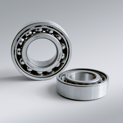
NSK NSK Angular Contact Ball Bearings ,C: Contact Angle of 15°, 7010CTYP5 ,D=50
NSK Angular Contact Ball Bearings ,C: Contact Angle of 15°, 7010CTYP5 ,D=50 Bearing Numbers Boundary Dimensions (mm) Basic Load Ratings (kN) Limiting Speeds (min-1) Factor f0 Mass (kg) approx. d D B r min. r1 min. Cr C0r Grease Oil 7010CTYP5 50 80 16 1 0.6 26 21.9 12000 17000 15.7 0.293 DESIGN, TYPES, AND FEATURES SINGLE-ROW ANGULAR CONTACT BALL BEARINGS Single-row angular contact ball bearings have a contact angle allowing them to sustain significant axial loads in one direction together with radial loads. Because of their design, when a radial load is applied, an axial force component is produced; therefore, two or more opposed bearings must be used. Since the rigidity of single-row angular contact ball bearings can be increased by preloading, they are often used in the main spindles of machine tools where high running accuracy is required (refer to Chapter 9 Preload on Page A192 for more information). Usually, the cages for angular contact ball bearings with a contact angle of 30° (designation A) or 40°(designation B) are made in accordance with Table 1, but depending on the application, machined synthetic-resin cages or molded polyamide-resin cages may also be used. The basic load ratings given in the bearing tables are based on standard cages. Though the figures in the bearing tables on Pages C086 to C101 for bearing bore diameters of 10 to 120 show bearings with single-shoulder inner rings, dual-shoulder bearings are also available. Please consult NSK for more detailed information. MATCHED ANGULAR CONTACT BALL BEARINGS The types and features of matched angular contact ball bearings are shown in Table 2. Table 2 Types and Features of Matched Angular Contact Ball Bearings Figure Arrangement Features Back-to-Back(DB)(Example)7208 A DB Radial loads and axial loads in both directions can be sustained. Since the distance between the effective load centers a0 is large, this type is suitable if moments are applied. Face-to-Face(DF)(Example)7208 B DF Radial loads and axial loads in both directions can be sustained. Compared with the DB Type, the distance between the effective load centers is small, so the capacity to sustain moments is inferior. Tandem(DT)(Example)7208 A DT Radial loads and axial loads in one direction can be sustained. Since two bearings share the axial load, this arrangement is used when the load in one direction is heavy. □Formulation of Bearing Designations Single-Row Matched Angular Contact Ball Bearings ①Bearing type 7 : Single-row angular contact ball bearings, matched angular contact ball bearings ②Dimension Series 2 : 02 Series, 3 : 03 Series, 9 : 19 Series, 0 : 10 Series ③Bore number Less than 03, Bearing bore 00 : 10mm, 01 : 12mm, 02 : 15mm, 03 : 17mmOver 04, Bearing bore Bore number ×5 (mm) ④Contact angle C : 15°, A5 : 25°, A : 30°, B : 40° ⑤Internal design EA : High Load Capacity ⑥Cage W : Pressed steel Cage, T85 : Machined brass cage (ball-guided),No designation : Machined brass cage (inner ring guided), TYN : Polyamide resin cage,T85 : Polyamide 46 resin cage, T7 : L-PPS resin cage ⑦Arrangement SU: Universal arrangement (single-row), DU : Universal arrangement (double-row),DB : Back-to-back arrangement, DF : Face-to-face arrangement, DT : Tandem arrangement ⑧Preload / Axial internal clearance EL : Extra light preload, L : Light preload, M : Medium preload, H : Heavy preloadOmitted : CN clearance, C3 : Clearance greater than CN, C4 : Clearance greater than C3,CNB : CN Clearance equivalent (universal arrangement) DOUBLE-ROW ANGULAR CONTACT BALL BEARINGS Double-row angular contact ball bearings are essentially a back- to-back mounting of two single-row angular contact ball bearings, but their inner and outer rings are each integrated into one. These bearings can sustain axial loads in both directions and offer good capacity for sustaining moment loads. They are often used as fixed- end bearings and contain cages made of pressed steel. □Formulation of Bearing Designations Double-Row Angular Contact Ball Bearings ①Bearing type 5 : Double-row angular contact ball bearings ②Dimension Series 2 : 02 Series 3: 03 Series ③Bore number 03 and under: 00 : 10mm, 01 : 12mm, 02 : 15mm, 03 : 17mm 04 and over: Bore diameter bore number ×5 (mm) ④Internal design ZZ: Steel shield on both sides, DDU: Rubber contact seal on both sides VV: Rubber noncontact seal on both sides ⑤Seals/shields Z: Steel shield on one sides, DU: Rubber contact seal on one side, V: Rubber non-contact seal on one side ⑥Grease* NS7: NS HI-LUBE
$116.02
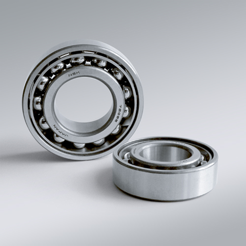
NSK NSK Angular Contact Ball Bearings ,C: Contact Angle of 15°, 7011CTYP5 ,D=55
NSK Angular Contact Ball Bearings ,C: Contact Angle of 15°, 7011CTYP5 ,D=55 Bearing Numbers Boundary Dimensions (mm) Basic Load Ratings (kN) Limiting Speeds (min-1) Factor f0 Mass (kg) approx. d D B r min. r1 min. Cr C0r Grease Oil 7011CTYP5 55 90 18 1.1 0.6 34 28.6 11000 15000 15.5 0.43 DESIGN, TYPES, AND FEATURES SINGLE-ROW ANGULAR CONTACT BALL BEARINGS Single-row angular contact ball bearings have a contact angle allowing them to sustain significant axial loads in one direction together with radial loads. Because of their design, when a radial load is applied, an axial force component is produced; therefore, two or more opposed bearings must be used. Since the rigidity of single-row angular contact ball bearings can be increased by preloading, they are often used in the main spindles of machine tools where high running accuracy is required (refer to Chapter 9 Preload on Page A192 for more information). Usually, the cages for angular contact ball bearings with a contact angle of 30° (designation A) or 40°(designation B) are made in accordance with Table 1, but depending on the application, machined synthetic-resin cages or molded polyamide-resin cages may also be used. The basic load ratings given in the bearing tables are based on standard cages. Though the figures in the bearing tables on Pages C086 to C101 for bearing bore diameters of 10 to 120 show bearings with single-shoulder inner rings, dual-shoulder bearings are also available. Please consult NSK for more detailed information. MATCHED ANGULAR CONTACT BALL BEARINGS The types and features of matched angular contact ball bearings are shown in Table 2. Table 2 Types and Features of Matched Angular Contact Ball Bearings Figure Arrangement Features Back-to-Back(DB)(Example)7208 A DB Radial loads and axial loads in both directions can be sustained. Since the distance between the effective load centers a0 is large, this type is suitable if moments are applied. Face-to-Face(DF)(Example)7208 B DF Radial loads and axial loads in both directions can be sustained. Compared with the DB Type, the distance between the effective load centers is small, so the capacity to sustain moments is inferior. Tandem(DT)(Example)7208 A DT Radial loads and axial loads in one direction can be sustained. Since two bearings share the axial load, this arrangement is used when the load in one direction is heavy. □Formulation of Bearing Designations Single-Row Matched Angular Contact Ball Bearings ①Bearing type 7 : Single-row angular contact ball bearings, matched angular contact ball bearings ②Dimension Series 2 : 02 Series, 3 : 03 Series, 9 : 19 Series, 0 : 10 Series ③Bore number Less than 03, Bearing bore 00 : 10mm, 01 : 12mm, 02 : 15mm, 03 : 17mmOver 04, Bearing bore Bore number ×5 (mm) ④Contact angle C : 15°, A5 : 25°, A : 30°, B : 40° ⑤Internal design EA : High Load Capacity ⑥Cage W : Pressed steel Cage, T85 : Machined brass cage (ball-guided),No designation : Machined brass cage (inner ring guided), TYN : Polyamide resin cage,T85 : Polyamide 46 resin cage, T7 : L-PPS resin cage ⑦Arrangement SU: Universal arrangement (single-row), DU : Universal arrangement (double-row),DB : Back-to-back arrangement, DF : Face-to-face arrangement, DT : Tandem arrangement ⑧Preload / Axial internal clearance EL : Extra light preload, L : Light preload, M : Medium preload, H : Heavy preloadOmitted : CN clearance, C3 : Clearance greater than CN, C4 : Clearance greater than C3,CNB : CN Clearance equivalent (universal arrangement) DOUBLE-ROW ANGULAR CONTACT BALL BEARINGS Double-row angular contact ball bearings are essentially a back- to-back mounting of two single-row angular contact ball bearings, but their inner and outer rings are each integrated into one. These bearings can sustain axial loads in both directions and offer good capacity for sustaining moment loads. They are often used as fixed- end bearings and contain cages made of pressed steel. □Formulation of Bearing Designations Double-Row Angular Contact Ball Bearings ①Bearing type 5 : Double-row angular contact ball bearings ②Dimension Series 2 : 02 Series 3: 03 Series ③Bore number 03 and under: 00 : 10mm, 01 : 12mm, 02 : 15mm, 03 : 17mm 04 and over: Bore diameter bore number ×5 (mm) ④Internal design ZZ: Steel shield on both sides, DDU: Rubber contact seal on both sides VV: Rubber noncontact seal on both sides ⑤Seals/shields Z: Steel shield on one sides, DU: Rubber contact seal on one side, V: Rubber non-contact seal on one side ⑥Grease* NS7: NS HI-LUBE
$139.30
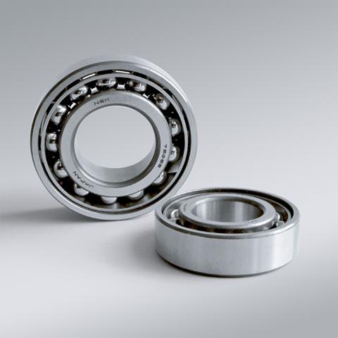
NSK NSK Angular Contact Ball Bearings ,C: Contact Angle of 15°, 7012CTYP5 ,D=60
NSK Angular Contact Ball Bearings ,C: Contact Angle of 15°, 7012CTYP5 ,D=60 Bearing Numbers Boundary Dimensions (mm) Basic Load Ratings (kN) Limiting Speeds (min-1) Factor f0 Mass (kg) approx. d D B r min. r1 min. Cr C0r Grease Oil 7012CTYP5 60 95 18 1.1 0.6 35 30.5 10000 14000 15.7 0.46 DESIGN, TYPES, AND FEATURES SINGLE-ROW ANGULAR CONTACT BALL BEARINGS Single-row angular contact ball bearings have a contact angle allowing them to sustain significant axial loads in one direction together with radial loads. Because of their design, when a radial load is applied, an axial force component is produced; therefore, two or more opposed bearings must be used. Since the rigidity of single-row angular contact ball bearings can be increased by preloading, they are often used in the main spindles of machine tools where high running accuracy is required (refer to Chapter 9 Preload on Page A192 for more information). Usually, the cages for angular contact ball bearings with a contact angle of 30° (designation A) or 40°(designation B) are made in accordance with Table 1, but depending on the application, machined synthetic-resin cages or molded polyamide-resin cages may also be used. The basic load ratings given in the bearing tables are based on standard cages. Though the figures in the bearing tables on Pages C086 to C101 for bearing bore diameters of 10 to 120 show bearings with single-shoulder inner rings, dual-shoulder bearings are also available. Please consult NSK for more detailed information. MATCHED ANGULAR CONTACT BALL BEARINGS The types and features of matched angular contact ball bearings are shown in Table 2. Table 2 Types and Features of Matched Angular Contact Ball Bearings Figure Arrangement Features Back-to-Back(DB)(Example)7208 A DB Radial loads and axial loads in both directions can be sustained. Since the distance between the effective load centers a0 is large, this type is suitable if moments are applied. Face-to-Face(DF)(Example)7208 B DF Radial loads and axial loads in both directions can be sustained. Compared with the DB Type, the distance between the effective load centers is small, so the capacity to sustain moments is inferior. Tandem(DT)(Example)7208 A DT Radial loads and axial loads in one direction can be sustained. Since two bearings share the axial load, this arrangement is used when the load in one direction is heavy. □Formulation of Bearing Designations Single-Row Matched Angular Contact Ball Bearings ①Bearing type 7 : Single-row angular contact ball bearings, matched angular contact ball bearings ②Dimension Series 2 : 02 Series, 3 : 03 Series, 9 : 19 Series, 0 : 10 Series ③Bore number Less than 03, Bearing bore 00 : 10mm, 01 : 12mm, 02 : 15mm, 03 : 17mmOver 04, Bearing bore Bore number ×5 (mm) ④Contact angle C : 15°, A5 : 25°, A : 30°, B : 40° ⑤Internal design EA : High Load Capacity ⑥Cage W : Pressed steel Cage, T85 : Machined brass cage (ball-guided),No designation : Machined brass cage (inner ring guided), TYN : Polyamide resin cage,T85 : Polyamide 46 resin cage, T7 : L-PPS resin cage ⑦Arrangement SU: Universal arrangement (single-row), DU : Universal arrangement (double-row),DB : Back-to-back arrangement, DF : Face-to-face arrangement, DT : Tandem arrangement ⑧Preload / Axial internal clearance EL : Extra light preload, L : Light preload, M : Medium preload, H : Heavy preloadOmitted : CN clearance, C3 : Clearance greater than CN, C4 : Clearance greater than C3,CNB : CN Clearance equivalent (universal arrangement) DOUBLE-ROW ANGULAR CONTACT BALL BEARINGS Double-row angular contact ball bearings are essentially a back- to-back mounting of two single-row angular contact ball bearings, but their inner and outer rings are each integrated into one. These bearings can sustain axial loads in both directions and offer good capacity for sustaining moment loads. They are often used as fixed- end bearings and contain cages made of pressed steel. □Formulation of Bearing Designations Double-Row Angular Contact Ball Bearings ①Bearing type 5 : Double-row angular contact ball bearings ②Dimension Series 2 : 02 Series 3: 03 Series ③Bore number 03 and under: 00 : 10mm, 01 : 12mm, 02 : 15mm, 03 : 17mm 04 and over: Bore diameter bore number ×5 (mm) ④Internal design ZZ: Steel shield on both sides, DDU: Rubber contact seal on both sides VV: Rubber noncontact seal on both sides ⑤Seals/shields Z: Steel shield on one sides, DU: Rubber contact seal on one side, V: Rubber non-contact seal on one side ⑥Grease* NS7: NS HI-LUBE
$141.81
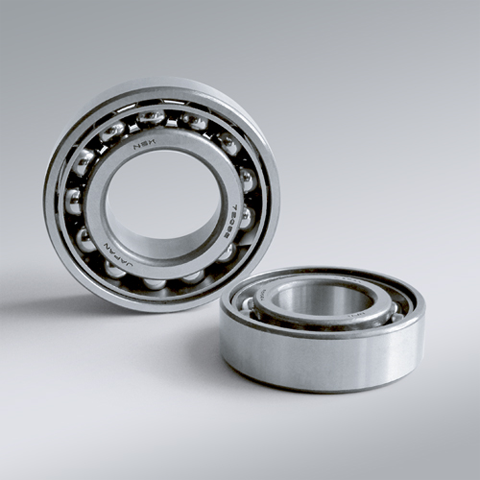
NSK NSK Angular Contact Ball Bearings ,C: Contact Angle of 15°, 7013CTYP5 ,D=65
NSK Angular Contact Ball Bearings ,C: Contact Angle of 15°, 7013CTYP5 ,D=65 Bearing Numbers Boundary Dimensions (mm) Basic Load Ratings (kN) Limiting Speeds (min-1) Factor f0 Mass (kg) approx. d D B r min. r1 min. Cr C0r Grease Oil 7013CTYP5 65 100 18 1.1 0.6 37 34.5 10000 13000 15.9 0.493 DESIGN, TYPES, AND FEATURES SINGLE-ROW ANGULAR CONTACT BALL BEARINGS Single-row angular contact ball bearings have a contact angle allowing them to sustain significant axial loads in one direction together with radial loads. Because of their design, when a radial load is applied, an axial force component is produced; therefore, two or more opposed bearings must be used. Since the rigidity of single-row angular contact ball bearings can be increased by preloading, they are often used in the main spindles of machine tools where high running accuracy is required (refer to Chapter 9 Preload on Page A192 for more information). Usually, the cages for angular contact ball bearings with a contact angle of 30° (designation A) or 40°(designation B) are made in accordance with Table 1, but depending on the application, machined synthetic-resin cages or molded polyamide-resin cages may also be used. The basic load ratings given in the bearing tables are based on standard cages. Though the figures in the bearing tables on Pages C086 to C101 for bearing bore diameters of 10 to 120 show bearings with single-shoulder inner rings, dual-shoulder bearings are also available. Please consult NSK for more detailed information. MATCHED ANGULAR CONTACT BALL BEARINGS The types and features of matched angular contact ball bearings are shown in Table 2. Table 2 Types and Features of Matched Angular Contact Ball Bearings Figure Arrangement Features Back-to-Back(DB)(Example)7208 A DB Radial loads and axial loads in both directions can be sustained. Since the distance between the effective load centers a0 is large, this type is suitable if moments are applied. Face-to-Face(DF)(Example)7208 B DF Radial loads and axial loads in both directions can be sustained. Compared with the DB Type, the distance between the effective load centers is small, so the capacity to sustain moments is inferior. Tandem(DT)(Example)7208 A DT Radial loads and axial loads in one direction can be sustained. Since two bearings share the axial load, this arrangement is used when the load in one direction is heavy. □Formulation of Bearing Designations Single-Row Matched Angular Contact Ball Bearings ①Bearing type 7 : Single-row angular contact ball bearings, matched angular contact ball bearings ②Dimension Series 2 : 02 Series, 3 : 03 Series, 9 : 19 Series, 0 : 10 Series ③Bore number Less than 03, Bearing bore 00 : 10mm, 01 : 12mm, 02 : 15mm, 03 : 17mmOver 04, Bearing bore Bore number ×5 (mm) ④Contact angle C : 15°, A5 : 25°, A : 30°, B : 40° ⑤Internal design EA : High Load Capacity ⑥Cage W : Pressed steel Cage, T85 : Machined brass cage (ball-guided),No designation : Machined brass cage (inner ring guided), TYN : Polyamide resin cage,T85 : Polyamide 46 resin cage, T7 : L-PPS resin cage ⑦Arrangement SU: Universal arrangement (single-row), DU : Universal arrangement (double-row),DB : Back-to-back arrangement, DF : Face-to-face arrangement, DT : Tandem arrangement ⑧Preload / Axial internal clearance EL : Extra light preload, L : Light preload, M : Medium preload, H : Heavy preloadOmitted : CN clearance, C3 : Clearance greater than CN, C4 : Clearance greater than C3,CNB : CN Clearance equivalent (universal arrangement) DOUBLE-ROW ANGULAR CONTACT BALL BEARINGS Double-row angular contact ball bearings are essentially a back- to-back mounting of two single-row angular contact ball bearings, but their inner and outer rings are each integrated into one. These bearings can sustain axial loads in both directions and offer good capacity for sustaining moment loads. They are often used as fixed- end bearings and contain cages made of pressed steel. □Formulation of Bearing Designations Double-Row Angular Contact Ball Bearings ①Bearing type 5 : Double-row angular contact ball bearings ②Dimension Series 2 : 02 Series 3: 03 Series ③Bore number 03 and under: 00 : 10mm, 01 : 12mm, 02 : 15mm, 03 : 17mm 04 and over: Bore diameter bore number ×5 (mm) ④Internal design ZZ: Steel shield on both sides, DDU: Rubber contact seal on both sides VV: Rubber noncontact seal on both sides ⑤Seals/shields Z: Steel shield on one sides, DU: Rubber contact seal on one side, V: Rubber non-contact seal on one side ⑥Grease* NS7: NS HI-LUBE
$170.37
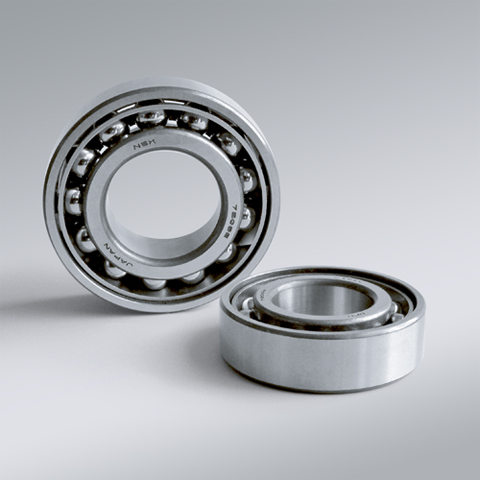
NSK NSK Angular Contact Ball Bearings ,C: Contact Angle of 15°, 7014CTYP5 ,D=70
NSK Angular Contact Ball Bearings ,C: Contact Angle of 15°, 7014CTYP5 ,D=70 Bearing Numbers Boundary Dimensions (mm) Basic Load Ratings (kN) Limiting Speeds (min-1) Factor f0 Mass (kg) approx. d D B r min. r1 min. Cr C0r Grease Oil 7014CTYP5 70 110 20 1.1 0.6 47 43 9000 12000 15.7 0.698 DESIGN, TYPES, AND FEATURES SINGLE-ROW ANGULAR CONTACT BALL BEARINGS Single-row angular contact ball bearings have a contact angle allowing them to sustain significant axial loads in one direction together with radial loads. Because of their design, when a radial load is applied, an axial force component is produced; therefore, two or more opposed bearings must be used. Since the rigidity of single-row angular contact ball bearings can be increased by preloading, they are often used in the main spindles of machine tools where high running accuracy is required (refer to Chapter 9 Preload on Page A192 for more information). Usually, the cages for angular contact ball bearings with a contact angle of 30° (designation A) or 40°(designation B) are made in accordance with Table 1, but depending on the application, machined synthetic-resin cages or molded polyamide-resin cages may also be used. The basic load ratings given in the bearing tables are based on standard cages. Though the figures in the bearing tables on Pages C086 to C101 for bearing bore diameters of 10 to 120 show bearings with single-shoulder inner rings, dual-shoulder bearings are also available. Please consult NSK for more detailed information. MATCHED ANGULAR CONTACT BALL BEARINGS The types and features of matched angular contact ball bearings are shown in Table 2. Table 2 Types and Features of Matched Angular Contact Ball Bearings Figure Arrangement Features Back-to-Back(DB)(Example)7208 A DB Radial loads and axial loads in both directions can be sustained. Since the distance between the effective load centers a0 is large, this type is suitable if moments are applied. Face-to-Face(DF)(Example)7208 B DF Radial loads and axial loads in both directions can be sustained. Compared with the DB Type, the distance between the effective load centers is small, so the capacity to sustain moments is inferior. Tandem(DT)(Example)7208 A DT Radial loads and axial loads in one direction can be sustained. Since two bearings share the axial load, this arrangement is used when the load in one direction is heavy. □Formulation of Bearing Designations Single-Row Matched Angular Contact Ball Bearings ①Bearing type 7 : Single-row angular contact ball bearings, matched angular contact ball bearings ②Dimension Series 2 : 02 Series, 3 : 03 Series, 9 : 19 Series, 0 : 10 Series ③Bore number Less than 03, Bearing bore 00 : 10mm, 01 : 12mm, 02 : 15mm, 03 : 17mmOver 04, Bearing bore Bore number ×5 (mm) ④Contact angle C : 15°, A5 : 25°, A : 30°, B : 40° ⑤Internal design EA : High Load Capacity ⑥Cage W : Pressed steel Cage, T85 : Machined brass cage (ball-guided),No designation : Machined brass cage (inner ring guided), TYN : Polyamide resin cage,T85 : Polyamide 46 resin cage, T7 : L-PPS resin cage ⑦Arrangement SU: Universal arrangement (single-row), DU : Universal arrangement (double-row),DB : Back-to-back arrangement, DF : Face-to-face arrangement, DT : Tandem arrangement ⑧Preload / Axial internal clearance EL : Extra light preload, L : Light preload, M : Medium preload, H : Heavy preloadOmitted : CN clearance, C3 : Clearance greater than CN, C4 : Clearance greater than C3,CNB : CN Clearance equivalent (universal arrangement) DOUBLE-ROW ANGULAR CONTACT BALL BEARINGS Double-row angular contact ball bearings are essentially a back- to-back mounting of two single-row angular contact ball bearings, but their inner and outer rings are each integrated into one. These bearings can sustain axial loads in both directions and offer good capacity for sustaining moment loads. They are often used as fixed- end bearings and contain cages made of pressed steel. □Formulation of Bearing Designations Double-Row Angular Contact Ball Bearings ①Bearing type 5 : Double-row angular contact ball bearings ②Dimension Series 2 : 02 Series 3: 03 Series ③Bore number 03 and under: 00 : 10mm, 01 : 12mm, 02 : 15mm, 03 : 17mm 04 and over: Bore diameter bore number ×5 (mm) ④Internal design ZZ: Steel shield on both sides, DDU: Rubber contact seal on both sides VV: Rubber noncontact seal on both sides ⑤Seals/shields Z: Steel shield on one sides, DU: Rubber contact seal on one side, V: Rubber non-contact seal on one side ⑥Grease* NS7: NS HI-LUBE
$194.74
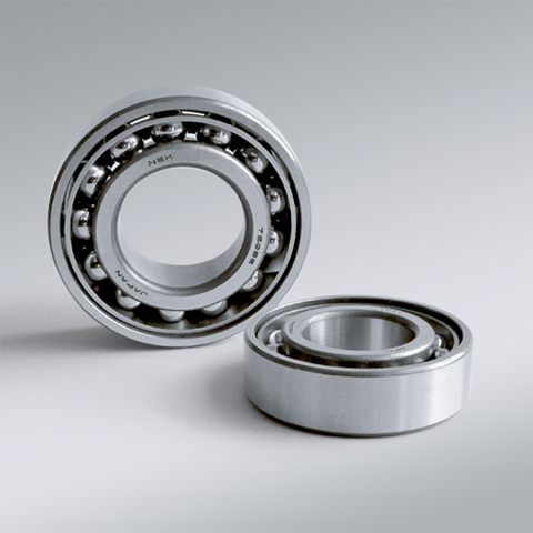
NSK NSK Angular Contact Ball Bearings ,C: Contact Angle of 15°, 7015CTYP5 ,D=75
NSK Angular Contact Ball Bearings ,C: Contact Angle of 15°, 7015CTYP5 ,D=75 Bearing Numbers Boundary Dimensions (mm) Basic Load Ratings (kN) Limiting Speeds (min-1) Factor f0 Mass (kg) approx. d D B r min. r1 min. Cr C0r Grease Oil 7015CTYP5 75 115 20 1.1 0.6 48 45.5 8500 12000 15.9 0.748 DESIGN, TYPES, AND FEATURES SINGLE-ROW ANGULAR CONTACT BALL BEARINGS Single-row angular contact ball bearings have a contact angle allowing them to sustain significant axial loads in one direction together with radial loads. Because of their design, when a radial load is applied, an axial force component is produced; therefore, two or more opposed bearings must be used. Since the rigidity of single-row angular contact ball bearings can be increased by preloading, they are often used in the main spindles of machine tools where high running accuracy is required (refer to Chapter 9 Preload on Page A192 for more information). Usually, the cages for angular contact ball bearings with a contact angle of 30° (designation A) or 40°(designation B) are made in accordance with Table 1, but depending on the application, machined synthetic-resin cages or molded polyamide-resin cages may also be used. The basic load ratings given in the bearing tables are based on standard cages. Though the figures in the bearing tables on Pages C086 to C101 for bearing bore diameters of 10 to 120 show bearings with single-shoulder inner rings, dual-shoulder bearings are also available. Please consult NSK for more detailed information. MATCHED ANGULAR CONTACT BALL BEARINGS The types and features of matched angular contact ball bearings are shown in Table 2. Table 2 Types and Features of Matched Angular Contact Ball Bearings Figure Arrangement Features Back-to-Back(DB)(Example)7208 A DB Radial loads and axial loads in both directions can be sustained. Since the distance between the effective load centers a0 is large, this type is suitable if moments are applied. Face-to-Face(DF)(Example)7208 B DF Radial loads and axial loads in both directions can be sustained. Compared with the DB Type, the distance between the effective load centers is small, so the capacity to sustain moments is inferior. Tandem(DT)(Example)7208 A DT Radial loads and axial loads in one direction can be sustained. Since two bearings share the axial load, this arrangement is used when the load in one direction is heavy. □Formulation of Bearing Designations Single-Row Matched Angular Contact Ball Bearings ①Bearing type 7 : Single-row angular contact ball bearings, matched angular contact ball bearings ②Dimension Series 2 : 02 Series, 3 : 03 Series, 9 : 19 Series, 0 : 10 Series ③Bore number Less than 03, Bearing bore 00 : 10mm, 01 : 12mm, 02 : 15mm, 03 : 17mmOver 04, Bearing bore Bore number ×5 (mm) ④Contact angle C : 15°, A5 : 25°, A : 30°, B : 40° ⑤Internal design EA : High Load Capacity ⑥Cage W : Pressed steel Cage, T85 : Machined brass cage (ball-guided),No designation : Machined brass cage (inner ring guided), TYN : Polyamide resin cage,T85 : Polyamide 46 resin cage, T7 : L-PPS resin cage ⑦Arrangement SU: Universal arrangement (single-row), DU : Universal arrangement (double-row),DB : Back-to-back arrangement, DF : Face-to-face arrangement, DT : Tandem arrangement ⑧Preload / Axial internal clearance EL : Extra light preload, L : Light preload, M : Medium preload, H : Heavy preloadOmitted : CN clearance, C3 : Clearance greater than CN, C4 : Clearance greater than C3,CNB : CN Clearance equivalent (universal arrangement) DOUBLE-ROW ANGULAR CONTACT BALL BEARINGS Double-row angular contact ball bearings are essentially a back- to-back mounting of two single-row angular contact ball bearings, but their inner and outer rings are each integrated into one. These bearings can sustain axial loads in both directions and offer good capacity for sustaining moment loads. They are often used as fixed- end bearings and contain cages made of pressed steel. □Formulation of Bearing Designations Double-Row Angular Contact Ball Bearings ①Bearing type 5 : Double-row angular contact ball bearings ②Dimension Series 2 : 02 Series 3: 03 Series ③Bore number 03 and under: 00 : 10mm, 01 : 12mm, 02 : 15mm, 03 : 17mm 04 and over: Bore diameter bore number ×5 (mm) ④Internal design ZZ: Steel shield on both sides, DDU: Rubber contact seal on both sides VV: Rubber noncontact seal on both sides ⑤Seals/shields Z: Steel shield on one sides, DU: Rubber contact seal on one side, V: Rubber non-contact seal on one side ⑥Grease* NS7: NS HI-LUBE
$239.10
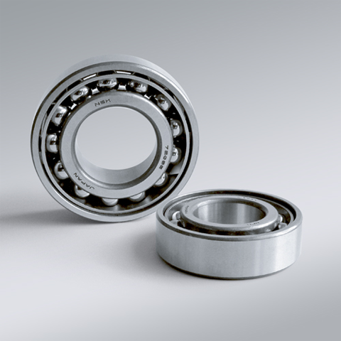
NSK NSK Angular Contact Ball Bearings ,C: Contact Angle of 15°, 7016CTYP5 ,D=80
NSK Angular Contact Ball Bearings ,C: Contact Angle of 15°, 7016CTYP5 ,D=80 Bearing Numbers Boundary Dimensions (mm) Basic Load Ratings (kN) Limiting Speeds (min-1) Factor f0 Mass (kg) approx. d D B r min. r1 min. Cr C0r Grease Oil 7016CTYP5 80 125 22 1.1 0.6 58.5 55.5 8000 11000 15.7 0.966 DESIGN, TYPES, AND FEATURES SINGLE-ROW ANGULAR CONTACT BALL BEARINGS Single-row angular contact ball bearings have a contact angle allowing them to sustain significant axial loads in one direction together with radial loads. Because of their design, when a radial load is applied, an axial force component is produced; therefore, two or more opposed bearings must be used. Since the rigidity of single-row angular contact ball bearings can be increased by preloading, they are often used in the main spindles of machine tools where high running accuracy is required (refer to Chapter 9 Preload on Page A192 for more information). Usually, the cages for angular contact ball bearings with a contact angle of 30° (designation A) or 40°(designation B) are made in accordance with Table 1, but depending on the application, machined synthetic-resin cages or molded polyamide-resin cages may also be used. The basic load ratings given in the bearing tables are based on standard cages. Though the figures in the bearing tables on Pages C086 to C101 for bearing bore diameters of 10 to 120 show bearings with single-shoulder inner rings, dual-shoulder bearings are also available. Please consult NSK for more detailed information. MATCHED ANGULAR CONTACT BALL BEARINGS The types and features of matched angular contact ball bearings are shown in Table 2. Table 2 Types and Features of Matched Angular Contact Ball Bearings Figure Arrangement Features Back-to-Back(DB)(Example)7208 A DB Radial loads and axial loads in both directions can be sustained. Since the distance between the effective load centers a0 is large, this type is suitable if moments are applied. Face-to-Face(DF)(Example)7208 B DF Radial loads and axial loads in both directions can be sustained. Compared with the DB Type, the distance between the effective load centers is small, so the capacity to sustain moments is inferior. Tandem(DT)(Example)7208 A DT Radial loads and axial loads in one direction can be sustained. Since two bearings share the axial load, this arrangement is used when the load in one direction is heavy. □Formulation of Bearing Designations Single-Row Matched Angular Contact Ball Bearings ①Bearing type 7 : Single-row angular contact ball bearings, matched angular contact ball bearings ②Dimension Series 2 : 02 Series, 3 : 03 Series, 9 : 19 Series, 0 : 10 Series ③Bore number Less than 03, Bearing bore 00 : 10mm, 01 : 12mm, 02 : 15mm, 03 : 17mmOver 04, Bearing bore Bore number ×5 (mm) ④Contact angle C : 15°, A5 : 25°, A : 30°, B : 40° ⑤Internal design EA : High Load Capacity ⑥Cage W : Pressed steel Cage, T85 : Machined brass cage (ball-guided),No designation : Machined brass cage (inner ring guided), TYN : Polyamide resin cage,T85 : Polyamide 46 resin cage, T7 : L-PPS resin cage ⑦Arrangement SU: Universal arrangement (single-row), DU : Universal arrangement (double-row),DB : Back-to-back arrangement, DF : Face-to-face arrangement, DT : Tandem arrangement ⑧Preload / Axial internal clearance EL : Extra light preload, L : Light preload, M : Medium preload, H : Heavy preloadOmitted : CN clearance, C3 : Clearance greater than CN, C4 : Clearance greater than C3,CNB : CN Clearance equivalent (universal arrangement) DOUBLE-ROW ANGULAR CONTACT BALL BEARINGS Double-row angular contact ball bearings are essentially a back- to-back mounting of two single-row angular contact ball bearings, but their inner and outer rings are each integrated into one. These bearings can sustain axial loads in both directions and offer good capacity for sustaining moment loads. They are often used as fixed- end bearings and contain cages made of pressed steel. □Formulation of Bearing Designations Double-Row Angular Contact Ball Bearings ①Bearing type 5 : Double-row angular contact ball bearings ②Dimension Series 2 : 02 Series 3: 03 Series ③Bore number 03 and under: 00 : 10mm, 01 : 12mm, 02 : 15mm, 03 : 17mm 04 and over: Bore diameter bore number ×5 (mm) ④Internal design ZZ: Steel shield on both sides, DDU: Rubber contact seal on both sides VV: Rubber noncontact seal on both sides ⑤Seals/shields Z: Steel shield on one sides, DU: Rubber contact seal on one side, V: Rubber non-contact seal on one side ⑥Grease* NS7: NS HI-LUBE
$290.21
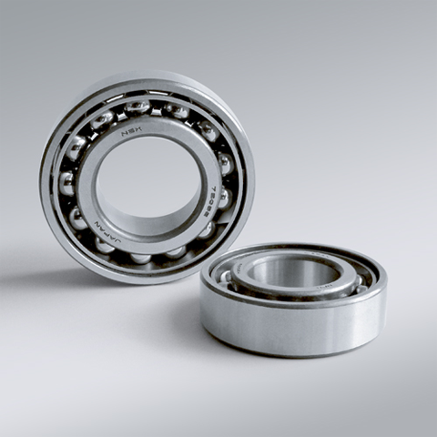
NSK NSK Angular Contact Ball Bearings ,C: Contact Angle of 15°, 7017CTYP5 ,D=85
NSK Angular Contact Ball Bearings ,C: Contact Angle of 15°, 7017CTYP5 ,D=85 Bearing Numbers Boundary Dimensions (mm) Basic Load Ratings (kN) Limiting Speeds (min-1) Factor f0 Mass (kg) approx. d D B r min. r1 min. Cr C0r Grease Oil 7017CTYP5 85 130 22 1.1 0.6 60 58.5 7500 10000 15.9 1.01 DESIGN, TYPES, AND FEATURES SINGLE-ROW ANGULAR CONTACT BALL BEARINGS Single-row angular contact ball bearings have a contact angle allowing them to sustain significant axial loads in one direction together with radial loads. Because of their design, when a radial load is applied, an axial force component is produced; therefore, two or more opposed bearings must be used. Since the rigidity of single-row angular contact ball bearings can be increased by preloading, they are often used in the main spindles of machine tools where high running accuracy is required (refer to Chapter 9 Preload on Page A192 for more information). Usually, the cages for angular contact ball bearings with a contact angle of 30° (designation A) or 40°(designation B) are made in accordance with Table 1, but depending on the application, machined synthetic-resin cages or molded polyamide-resin cages may also be used. The basic load ratings given in the bearing tables are based on standard cages. Though the figures in the bearing tables on Pages C086 to C101 for bearing bore diameters of 10 to 120 show bearings with single-shoulder inner rings, dual-shoulder bearings are also available. Please consult NSK for more detailed information. MATCHED ANGULAR CONTACT BALL BEARINGS The types and features of matched angular contact ball bearings are shown in Table 2. Table 2 Types and Features of Matched Angular Contact Ball Bearings Figure Arrangement Features Back-to-Back(DB)(Example)7208 A DB Radial loads and axial loads in both directions can be sustained. Since the distance between the effective load centers a0 is large, this type is suitable if moments are applied. Face-to-Face(DF)(Example)7208 B DF Radial loads and axial loads in both directions can be sustained. Compared with the DB Type, the distance between the effective load centers is small, so the capacity to sustain moments is inferior. Tandem(DT)(Example)7208 A DT Radial loads and axial loads in one direction can be sustained. Since two bearings share the axial load, this arrangement is used when the load in one direction is heavy. □Formulation of Bearing Designations Single-Row Matched Angular Contact Ball Bearings ①Bearing type 7 : Single-row angular contact ball bearings, matched angular contact ball bearings ②Dimension Series 2 : 02 Series, 3 : 03 Series, 9 : 19 Series, 0 : 10 Series ③Bore number Less than 03, Bearing bore 00 : 10mm, 01 : 12mm, 02 : 15mm, 03 : 17mmOver 04, Bearing bore Bore number ×5 (mm) ④Contact angle C : 15°, A5 : 25°, A : 30°, B : 40° ⑤Internal design EA : High Load Capacity ⑥Cage W : Pressed steel Cage, T85 : Machined brass cage (ball-guided),No designation : Machined brass cage (inner ring guided), TYN : Polyamide resin cage,T85 : Polyamide 46 resin cage, T7 : L-PPS resin cage ⑦Arrangement SU: Universal arrangement (single-row), DU : Universal arrangement (double-row),DB : Back-to-back arrangement, DF : Face-to-face arrangement, DT : Tandem arrangement ⑧Preload / Axial internal clearance EL : Extra light preload, L : Light preload, M : Medium preload, H : Heavy preloadOmitted : CN clearance, C3 : Clearance greater than CN, C4 : Clearance greater than C3,CNB : CN Clearance equivalent (universal arrangement) DOUBLE-ROW ANGULAR CONTACT BALL BEARINGS Double-row angular contact ball bearings are essentially a back- to-back mounting of two single-row angular contact ball bearings, but their inner and outer rings are each integrated into one. These bearings can sustain axial loads in both directions and offer good capacity for sustaining moment loads. They are often used as fixed- end bearings and contain cages made of pressed steel. □Formulation of Bearing Designations Double-Row Angular Contact Ball Bearings ①Bearing type 5 : Double-row angular contact ball bearings ②Dimension Series 2 : 02 Series 3: 03 Series ③Bore number 03 and under: 00 : 10mm, 01 : 12mm, 02 : 15mm, 03 : 17mm 04 and over: Bore diameter bore number ×5 (mm) ④Internal design ZZ: Steel shield on both sides, DDU: Rubber contact seal on both sides VV: Rubber noncontact seal on both sides ⑤Seals/shields Z: Steel shield on one sides, DU: Rubber contact seal on one side, V: Rubber non-contact seal on one side ⑥Grease* NS7: NS HI-LUBE
$334.70
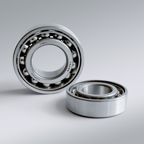
NSK NSK Angular Contact Ball Bearings ,C: Contact Angle of 15°, 7018CTYP5 ,D=90
NSK Angular Contact Ball Bearings ,C: Contact Angle of 15°, 7018CTYP5 ,D=90 Bearing Numbers Boundary Dimensions (mm) Basic Load Ratings (kN) Limiting Speeds (min-1) Factor f0 Mass (kg) approx. d D B r min. r1 min. Cr C0r Grease Oil 7018CTYP5 90 140 24 1.5 1 71.5 69 7100 9500 15.7 1.34 DESIGN, TYPES, AND FEATURES SINGLE-ROW ANGULAR CONTACT BALL BEARINGS Single-row angular contact ball bearings have a contact angle allowing them to sustain significant axial loads in one direction together with radial loads. Because of their design, when a radial load is applied, an axial force component is produced; therefore, two or more opposed bearings must be used. Since the rigidity of single-row angular contact ball bearings can be increased by preloading, they are often used in the main spindles of machine tools where high running accuracy is required (refer to Chapter 9 Preload on Page A192 for more information). Usually, the cages for angular contact ball bearings with a contact angle of 30° (designation A) or 40°(designation B) are made in accordance with Table 1, but depending on the application, machined synthetic-resin cages or molded polyamide-resin cages may also be used. The basic load ratings given in the bearing tables are based on standard cages. Though the figures in the bearing tables on Pages C086 to C101 for bearing bore diameters of 10 to 120 show bearings with single-shoulder inner rings, dual-shoulder bearings are also available. Please consult NSK for more detailed information. MATCHED ANGULAR CONTACT BALL BEARINGS The types and features of matched angular contact ball bearings are shown in Table 2. Table 2 Types and Features of Matched Angular Contact Ball Bearings Figure Arrangement Features Back-to-Back(DB)(Example)7208 A DB Radial loads and axial loads in both directions can be sustained. Since the distance between the effective load centers a0 is large, this type is suitable if moments are applied. Face-to-Face(DF)(Example)7208 B DF Radial loads and axial loads in both directions can be sustained. Compared with the DB Type, the distance between the effective load centers is small, so the capacity to sustain moments is inferior. Tandem(DT)(Example)7208 A DT Radial loads and axial loads in one direction can be sustained. Since two bearings share the axial load, this arrangement is used when the load in one direction is heavy. □Formulation of Bearing Designations Single-Row Matched Angular Contact Ball Bearings ①Bearing type 7 : Single-row angular contact ball bearings, matched angular contact ball bearings ②Dimension Series 2 : 02 Series, 3 : 03 Series, 9 : 19 Series, 0 : 10 Series ③Bore number Less than 03, Bearing bore 00 : 10mm, 01 : 12mm, 02 : 15mm, 03 : 17mmOver 04, Bearing bore Bore number ×5 (mm) ④Contact angle C : 15°, A5 : 25°, A : 30°, B : 40° ⑤Internal design EA : High Load Capacity ⑥Cage W : Pressed steel Cage, T85 : Machined brass cage (ball-guided),No designation : Machined brass cage (inner ring guided), TYN : Polyamide resin cage,T85 : Polyamide 46 resin cage, T7 : L-PPS resin cage ⑦Arrangement SU: Universal arrangement (single-row), DU : Universal arrangement (double-row),DB : Back-to-back arrangement, DF : Face-to-face arrangement, DT : Tandem arrangement ⑧Preload / Axial internal clearance EL : Extra light preload, L : Light preload, M : Medium preload, H : Heavy preloadOmitted : CN clearance, C3 : Clearance greater than CN, C4 : Clearance greater than C3,CNB : CN Clearance equivalent (universal arrangement) DOUBLE-ROW ANGULAR CONTACT BALL BEARINGS Double-row angular contact ball bearings are essentially a back- to-back mounting of two single-row angular contact ball bearings, but their inner and outer rings are each integrated into one. These bearings can sustain axial loads in both directions and offer good capacity for sustaining moment loads. They are often used as fixed- end bearings and contain cages made of pressed steel. □Formulation of Bearing Designations Double-Row Angular Contact Ball Bearings ①Bearing type 5 : Double-row angular contact ball bearings ②Dimension Series 2 : 02 Series 3: 03 Series ③Bore number 03 and under: 00 : 10mm, 01 : 12mm, 02 : 15mm, 03 : 17mm 04 and over: Bore diameter bore number ×5 (mm) ④Internal design ZZ: Steel shield on both sides, DDU: Rubber contact seal on both sides VV: Rubber noncontact seal on both sides ⑤Seals/shields Z: Steel shield on one sides, DU: Rubber contact seal on one side, V: Rubber non-contact seal on one side ⑥Grease* NS7: NS HI-LUBE
$363.38
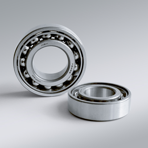
NSK NSK Angular Contact Ball Bearings ,C: Contact Angle of 15°, 7019CTYP5 ,D=95
NSK Angular Contact Ball Bearings ,C: Contact Angle of 15°, 7019CTYP5 ,D=95 Bearing Numbers Boundary Dimensions (mm) Basic Load Ratings (kN) Limiting Speeds (min-1) Factor f0 Mass (kg) approx. d D B r min. r1 min. Cr C0r Grease Oil 7019CTYP5 95 145 24 1.5 1 73.5 73 6700 9000 15.9 1.42 DESIGN, TYPES, AND FEATURES SINGLE-ROW ANGULAR CONTACT BALL BEARINGS Single-row angular contact ball bearings have a contact angle allowing them to sustain significant axial loads in one direction together with radial loads. Because of their design, when a radial load is applied, an axial force component is produced; therefore, two or more opposed bearings must be used. Since the rigidity of single-row angular contact ball bearings can be increased by preloading, they are often used in the main spindles of machine tools where high running accuracy is required (refer to Chapter 9 Preload on Page A192 for more information). Usually, the cages for angular contact ball bearings with a contact angle of 30° (designation A) or 40°(designation B) are made in accordance with Table 1, but depending on the application, machined synthetic-resin cages or molded polyamide-resin cages may also be used. The basic load ratings given in the bearing tables are based on standard cages. Though the figures in the bearing tables on Pages C086 to C101 for bearing bore diameters of 10 to 120 show bearings with single-shoulder inner rings, dual-shoulder bearings are also available. Please consult NSK for more detailed information. MATCHED ANGULAR CONTACT BALL BEARINGS The types and features of matched angular contact ball bearings are shown in Table 2. Table 2 Types and Features of Matched Angular Contact Ball Bearings Figure Arrangement Features Back-to-Back(DB)(Example)7208 A DB Radial loads and axial loads in both directions can be sustained. Since the distance between the effective load centers a0 is large, this type is suitable if moments are applied. Face-to-Face(DF)(Example)7208 B DF Radial loads and axial loads in both directions can be sustained. Compared with the DB Type, the distance between the effective load centers is small, so the capacity to sustain moments is inferior. Tandem(DT)(Example)7208 A DT Radial loads and axial loads in one direction can be sustained. Since two bearings share the axial load, this arrangement is used when the load in one direction is heavy. □Formulation of Bearing Designations Single-Row Matched Angular Contact Ball Bearings ①Bearing type 7 : Single-row angular contact ball bearings, matched angular contact ball bearings ②Dimension Series 2 : 02 Series, 3 : 03 Series, 9 : 19 Series, 0 : 10 Series ③Bore number Less than 03, Bearing bore 00 : 10mm, 01 : 12mm, 02 : 15mm, 03 : 17mmOver 04, Bearing bore Bore number ×5 (mm) ④Contact angle C : 15°, A5 : 25°, A : 30°, B : 40° ⑤Internal design EA : High Load Capacity ⑥Cage W : Pressed steel Cage, T85 : Machined brass cage (ball-guided),No designation : Machined brass cage (inner ring guided), TYN : Polyamide resin cage,T85 : Polyamide 46 resin cage, T7 : L-PPS resin cage ⑦Arrangement SU: Universal arrangement (single-row), DU : Universal arrangement (double-row),DB : Back-to-back arrangement, DF : Face-to-face arrangement, DT : Tandem arrangement ⑧Preload / Axial internal clearance EL : Extra light preload, L : Light preload, M : Medium preload, H : Heavy preloadOmitted : CN clearance, C3 : Clearance greater than CN, C4 : Clearance greater than C3,CNB : CN Clearance equivalent (universal arrangement) DOUBLE-ROW ANGULAR CONTACT BALL BEARINGS Double-row angular contact ball bearings are essentially a back- to-back mounting of two single-row angular contact ball bearings, but their inner and outer rings are each integrated into one. These bearings can sustain axial loads in both directions and offer good capacity for sustaining moment loads. They are often used as fixed- end bearings and contain cages made of pressed steel. □Formulation of Bearing Designations Double-Row Angular Contact Ball Bearings ①Bearing type 5 : Double-row angular contact ball bearings ②Dimension Series 2 : 02 Series 3: 03 Series ③Bore number 03 and under: 00 : 10mm, 01 : 12mm, 02 : 15mm, 03 : 17mm 04 and over: Bore diameter bore number ×5 (mm) ④Internal design ZZ: Steel shield on both sides, DDU: Rubber contact seal on both sides VV: Rubber noncontact seal on both sides ⑤Seals/shields Z: Steel shield on one sides, DU: Rubber contact seal on one side, V: Rubber non-contact seal on one side ⑥Grease* NS7: NS HI-LUBE
$416.16
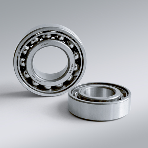
NSK NSK Angular Contact Ball Bearings ,C: Contact Angle of 15°, 7020CTYP5 ,D=100
NSK Angular Contact Ball Bearings ,C: Contact Angle of 15°, 7020CTYP5 ,D=100 Bearing Numbers Boundary Dimensions (mm) Basic Load Ratings (kN) Limiting Speeds (min-1) Factor f0 Mass (kg) approx. d D B r min. r1 min. Cr C0r Grease Oil 7020CTYP5 100 150 24 1.5 1 75.5 77 6300 9000 16 1.46 DESIGN, TYPES, AND FEATURES SINGLE-ROW ANGULAR CONTACT BALL BEARINGS Single-row angular contact ball bearings have a contact angle allowing them to sustain significant axial loads in one direction together with radial loads. Because of their design, when a radial load is applied, an axial force component is produced; therefore, two or more opposed bearings must be used. Since the rigidity of single-row angular contact ball bearings can be increased by preloading, they are often used in the main spindles of machine tools where high running accuracy is required (refer to Chapter 9 Preload on Page A192 for more information). Usually, the cages for angular contact ball bearings with a contact angle of 30° (designation A) or 40°(designation B) are made in accordance with Table 1, but depending on the application, machined synthetic-resin cages or molded polyamide-resin cages may also be used. The basic load ratings given in the bearing tables are based on standard cages. Though the figures in the bearing tables on Pages C086 to C101 for bearing bore diameters of 10 to 120 show bearings with single-shoulder inner rings, dual-shoulder bearings are also available. Please consult NSK for more detailed information. MATCHED ANGULAR CONTACT BALL BEARINGS The types and features of matched angular contact ball bearings are shown in Table 2. Table 2 Types and Features of Matched Angular Contact Ball Bearings Figure Arrangement Features Back-to-Back(DB)(Example)7208 A DB Radial loads and axial loads in both directions can be sustained. Since the distance between the effective load centers a0 is large, this type is suitable if moments are applied. Face-to-Face(DF)(Example)7208 B DF Radial loads and axial loads in both directions can be sustained. Compared with the DB Type, the distance between the effective load centers is small, so the capacity to sustain moments is inferior. Tandem(DT)(Example)7208 A DT Radial loads and axial loads in one direction can be sustained. Since two bearings share the axial load, this arrangement is used when the load in one direction is heavy. □Formulation of Bearing Designations Single-Row Matched Angular Contact Ball Bearings ①Bearing type 7 : Single-row angular contact ball bearings, matched angular contact ball bearings ②Dimension Series 2 : 02 Series, 3 : 03 Series, 9 : 19 Series, 0 : 10 Series ③Bore number Less than 03, Bearing bore 00 : 10mm, 01 : 12mm, 02 : 15mm, 03 : 17mmOver 04, Bearing bore Bore number ×5 (mm) ④Contact angle C : 15°, A5 : 25°, A : 30°, B : 40° ⑤Internal design EA : High Load Capacity ⑥Cage W : Pressed steel Cage, T85 : Machined brass cage (ball-guided),No designation : Machined brass cage (inner ring guided), TYN : Polyamide resin cage,T85 : Polyamide 46 resin cage, T7 : L-PPS resin cage ⑦Arrangement SU: Universal arrangement (single-row), DU : Universal arrangement (double-row),DB : Back-to-back arrangement, DF : Face-to-face arrangement, DT : Tandem arrangement ⑧Preload / Axial internal clearance EL : Extra light preload, L : Light preload, M : Medium preload, H : Heavy preloadOmitted : CN clearance, C3 : Clearance greater than CN, C4 : Clearance greater than C3,CNB : CN Clearance equivalent (universal arrangement) DOUBLE-ROW ANGULAR CONTACT BALL BEARINGS Double-row angular contact ball bearings are essentially a back- to-back mounting of two single-row angular contact ball bearings, but their inner and outer rings are each integrated into one. These bearings can sustain axial loads in both directions and offer good capacity for sustaining moment loads. They are often used as fixed- end bearings and contain cages made of pressed steel. □Formulation of Bearing Designations Double-Row Angular Contact Ball Bearings ①Bearing type 5 : Double-row angular contact ball bearings ②Dimension Series 2 : 02 Series 3: 03 Series ③Bore number 03 and under: 00 : 10mm, 01 : 12mm, 02 : 15mm, 03 : 17mm 04 and over: Bore diameter bore number ×5 (mm) ④Internal design ZZ: Steel shield on both sides, DDU: Rubber contact seal on both sides VV: Rubber noncontact seal on both sides ⑤Seals/shields Z: Steel shield on one sides, DU: Rubber contact seal on one side, V: Rubber non-contact seal on one side ⑥Grease* NS7: NS HI-LUBE
$434.34
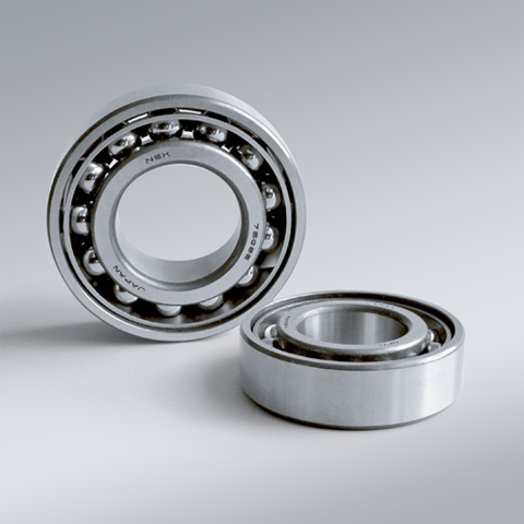
NSK NSK Angular Contact Ball Bearings ,C: Contact Angle of 15°, 7200CTYP5 ,D=10
NSK Angular Contact Ball Bearings ,C: Contact Angle of 15°, 7200CTYP5 ,D=10 Bearing Numbers Boundary Dimensions (mm) Basic Load Ratings (kN) Limiting Speeds (min-1) Factor f0 Mass (kg) approx. d D B r min. r1 min. Cr C0r Grease Oil 7200CTYP5 10 30 9 0.6 0.3 5.4 2.61 40000 56000 13.2 0.032 DESIGN, TYPES, AND FEATURES SINGLE-ROW ANGULAR CONTACT BALL BEARINGS Single-row angular contact ball bearings have a contact angle allowing them to sustain significant axial loads in one direction together with radial loads. Because of their design, when a radial load is applied, an axial force component is produced; therefore, two or more opposed bearings must be used. Since the rigidity of single-row angular contact ball bearings can be increased by preloading, they are often used in the main spindles of machine tools where high running accuracy is required (refer to Chapter 9 Preload on Page A192 for more information). Usually, the cages for angular contact ball bearings with a contact angle of 30° (designation A) or 40°(designation B) are made in accordance with Table 1, but depending on the application, machined synthetic-resin cages or molded polyamide-resin cages may also be used. The basic load ratings given in the bearing tables are based on standard cages. Though the figures in the bearing tables on Pages C086 to C101 for bearing bore diameters of 10 to 120 show bearings with single-shoulder inner rings, dual-shoulder bearings are also available. Please consult NSK for more detailed information. MATCHED ANGULAR CONTACT BALL BEARINGS The types and features of matched angular contact ball bearings are shown in Table 2. Table 2 Types and Features of Matched Angular Contact Ball Bearings Figure Arrangement Features Back-to-Back(DB)(Example)7208 A DB Radial loads and axial loads in both directions can be sustained. Since the distance between the effective load centers a0 is large, this type is suitable if moments are applied. Face-to-Face(DF)(Example)7208 B DF Radial loads and axial loads in both directions can be sustained. Compared with the DB Type, the distance between the effective load centers is small, so the capacity to sustain moments is inferior. Tandem(DT)(Example)7208 A DT Radial loads and axial loads in one direction can be sustained. Since two bearings share the axial load, this arrangement is used when the load in one direction is heavy. □Formulation of Bearing Designations Single-Row Matched Angular Contact Ball Bearings ①Bearing type 7 : Single-row angular contact ball bearings, matched angular contact ball bearings ②Dimension Series 2 : 02 Series, 3 : 03 Series, 9 : 19 Series, 0 : 10 Series ③Bore number Less than 03, Bearing bore 00 : 10mm, 01 : 12mm, 02 : 15mm, 03 : 17mmOver 04, Bearing bore Bore number ×5 (mm) ④Contact angle C : 15°, A5 : 25°, A : 30°, B : 40° ⑤Internal design EA : High Load Capacity ⑥Cage W : Pressed steel Cage, T85 : Machined brass cage (ball-guided),No designation : Machined brass cage (inner ring guided), TYN : Polyamide resin cage,T85 : Polyamide 46 resin cage, T7 : L-PPS resin cage ⑦Arrangement SU: Universal arrangement (single-row), DU : Universal arrangement (double-row),DB : Back-to-back arrangement, DF : Face-to-face arrangement, DT : Tandem arrangement ⑧Preload / Axial internal clearance EL : Extra light preload, L : Light preload, M : Medium preload, H : Heavy preloadOmitted : CN clearance, C3 : Clearance greater than CN, C4 : Clearance greater than C3,CNB : CN Clearance equivalent (universal arrangement) DOUBLE-ROW ANGULAR CONTACT BALL BEARINGS Double-row angular contact ball bearings are essentially a back- to-back mounting of two single-row angular contact ball bearings, but their inner and outer rings are each integrated into one. These bearings can sustain axial loads in both directions and offer good capacity for sustaining moment loads. They are often used as fixed- end bearings and contain cages made of pressed steel. □Formulation of Bearing Designations Double-Row Angular Contact Ball Bearings ①Bearing type 5 : Double-row angular contact ball bearings ②Dimension Series 2 : 02 Series 3: 03 Series ③Bore number 03 and under: 00 : 10mm, 01 : 12mm, 02 : 15mm, 03 : 17mm 04 and over: Bore diameter bore number ×5 (mm) ④Internal design ZZ: Steel shield on both sides, DDU: Rubber contact seal on both sides VV: Rubber noncontact seal on both sides ⑤Seals/shields Z: Steel shield on one sides, DU: Rubber contact seal on one side, V: Rubber non-contact seal on one side ⑥Grease* NS7: NS HI-LUBE
$45.32
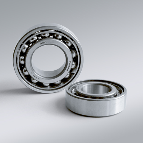
NSK NSK Angular Contact Ball Bearings ,C: Contact Angle of 15°, 7201CTYP5 ,D=12
NSK Angular Contact Ball Bearings ,C: Contact Angle of 15°, 7201CTYP5 ,D=12 Bearing Numbers Boundary Dimensions (mm) Basic Load Ratings (kN) Limiting Speeds (min-1) Factor f0 Mass (kg) approx. d D B r min. r1 min. Cr C0r Grease Oil 7201CTYP5 12 32 10 0.6 0.3 7.9 3.85 36000 50000 12.5 0.036 DESIGN, TYPES, AND FEATURES SINGLE-ROW ANGULAR CONTACT BALL BEARINGS Single-row angular contact ball bearings have a contact angle allowing them to sustain significant axial loads in one direction together with radial loads. Because of their design, when a radial load is applied, an axial force component is produced; therefore, two or more opposed bearings must be used. Since the rigidity of single-row angular contact ball bearings can be increased by preloading, they are often used in the main spindles of machine tools where high running accuracy is required (refer to Chapter 9 Preload on Page A192 for more information). Usually, the cages for angular contact ball bearings with a contact angle of 30° (designation A) or 40°(designation B) are made in accordance with Table 1, but depending on the application, machined synthetic-resin cages or molded polyamide-resin cages may also be used. The basic load ratings given in the bearing tables are based on standard cages. Though the figures in the bearing tables on Pages C086 to C101 for bearing bore diameters of 10 to 120 show bearings with single-shoulder inner rings, dual-shoulder bearings are also available. Please consult NSK for more detailed information. MATCHED ANGULAR CONTACT BALL BEARINGS The types and features of matched angular contact ball bearings are shown in Table 2. Table 2 Types and Features of Matched Angular Contact Ball Bearings Figure Arrangement Features Back-to-Back(DB)(Example)7208 A DB Radial loads and axial loads in both directions can be sustained. Since the distance between the effective load centers a0 is large, this type is suitable if moments are applied. Face-to-Face(DF)(Example)7208 B DF Radial loads and axial loads in both directions can be sustained. Compared with the DB Type, the distance between the effective load centers is small, so the capacity to sustain moments is inferior. Tandem(DT)(Example)7208 A DT Radial loads and axial loads in one direction can be sustained. Since two bearings share the axial load, this arrangement is used when the load in one direction is heavy. □Formulation of Bearing Designations Single-Row Matched Angular Contact Ball Bearings ①Bearing type 7 : Single-row angular contact ball bearings, matched angular contact ball bearings ②Dimension Series 2 : 02 Series, 3 : 03 Series, 9 : 19 Series, 0 : 10 Series ③Bore number Less than 03, Bearing bore 00 : 10mm, 01 : 12mm, 02 : 15mm, 03 : 17mmOver 04, Bearing bore Bore number ×5 (mm) ④Contact angle C : 15°, A5 : 25°, A : 30°, B : 40° ⑤Internal design EA : High Load Capacity ⑥Cage W : Pressed steel Cage, T85 : Machined brass cage (ball-guided),No designation : Machined brass cage (inner ring guided), TYN : Polyamide resin cage,T85 : Polyamide 46 resin cage, T7 : L-PPS resin cage ⑦Arrangement SU: Universal arrangement (single-row), DU : Universal arrangement (double-row),DB : Back-to-back arrangement, DF : Face-to-face arrangement, DT : Tandem arrangement ⑧Preload / Axial internal clearance EL : Extra light preload, L : Light preload, M : Medium preload, H : Heavy preloadOmitted : CN clearance, C3 : Clearance greater than CN, C4 : Clearance greater than C3,CNB : CN Clearance equivalent (universal arrangement) DOUBLE-ROW ANGULAR CONTACT BALL BEARINGS Double-row angular contact ball bearings are essentially a back- to-back mounting of two single-row angular contact ball bearings, but their inner and outer rings are each integrated into one. These bearings can sustain axial loads in both directions and offer good capacity for sustaining moment loads. They are often used as fixed- end bearings and contain cages made of pressed steel. □Formulation of Bearing Designations Double-Row Angular Contact Ball Bearings ①Bearing type 5 : Double-row angular contact ball bearings ②Dimension Series 2 : 02 Series 3: 03 Series ③Bore number 03 and under: 00 : 10mm, 01 : 12mm, 02 : 15mm, 03 : 17mm 04 and over: Bore diameter bore number ×5 (mm) ④Internal design ZZ: Steel shield on both sides, DDU: Rubber contact seal on both sides VV: Rubber noncontact seal on both sides ⑤Seals/shields Z: Steel shield on one sides, DU: Rubber contact seal on one side, V: Rubber non-contact seal on one side ⑥Grease* NS7: NS HI-LUBE
$46.42
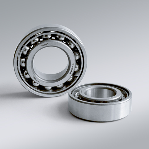
NSK NSK Angular Contact Ball Bearings ,C: Contact Angle of 15°, 7202CTYP5 ,D=15
NSK Angular Contact Ball Bearings ,C: Contact Angle of 15°, 7202CTYP5 ,D=15 Bearing Numbers Boundary Dimensions (mm) Basic Load Ratings (kN) Limiting Speeds (min-1) Factor f0 Mass (kg) approx. d D B r min. r1 min. Cr C0r Grease Oil 7202CTYP5 15 35 11 0.6 0.3 8.65 4.55 32000 45000 13.2 0.045 DESIGN, TYPES, AND FEATURES SINGLE-ROW ANGULAR CONTACT BALL BEARINGS Single-row angular contact ball bearings have a contact angle allowing them to sustain significant axial loads in one direction together with radial loads. Because of their design, when a radial load is applied, an axial force component is produced; therefore, two or more opposed bearings must be used. Since the rigidity of single-row angular contact ball bearings can be increased by preloading, they are often used in the main spindles of machine tools where high running accuracy is required (refer to Chapter 9 Preload on Page A192 for more information). Usually, the cages for angular contact ball bearings with a contact angle of 30° (designation A) or 40°(designation B) are made in accordance with Table 1, but depending on the application, machined synthetic-resin cages or molded polyamide-resin cages may also be used. The basic load ratings given in the bearing tables are based on standard cages. Though the figures in the bearing tables on Pages C086 to C101 for bearing bore diameters of 10 to 120 show bearings with single-shoulder inner rings, dual-shoulder bearings are also available. Please consult NSK for more detailed information. MATCHED ANGULAR CONTACT BALL BEARINGS The types and features of matched angular contact ball bearings are shown in Table 2. Table 2 Types and Features of Matched Angular Contact Ball Bearings Figure Arrangement Features Back-to-Back(DB)(Example)7208 A DB Radial loads and axial loads in both directions can be sustained. Since the distance between the effective load centers a0 is large, this type is suitable if moments are applied. Face-to-Face(DF)(Example)7208 B DF Radial loads and axial loads in both directions can be sustained. Compared with the DB Type, the distance between the effective load centers is small, so the capacity to sustain moments is inferior. Tandem(DT)(Example)7208 A DT Radial loads and axial loads in one direction can be sustained. Since two bearings share the axial load, this arrangement is used when the load in one direction is heavy. □Formulation of Bearing Designations Single-Row Matched Angular Contact Ball Bearings ①Bearing type 7 : Single-row angular contact ball bearings, matched angular contact ball bearings ②Dimension Series 2 : 02 Series, 3 : 03 Series, 9 : 19 Series, 0 : 10 Series ③Bore number Less than 03, Bearing bore 00 : 10mm, 01 : 12mm, 02 : 15mm, 03 : 17mmOver 04, Bearing bore Bore number ×5 (mm) ④Contact angle C : 15°, A5 : 25°, A : 30°, B : 40° ⑤Internal design EA : High Load Capacity ⑥Cage W : Pressed steel Cage, T85 : Machined brass cage (ball-guided),No designation : Machined brass cage (inner ring guided), TYN : Polyamide resin cage,T85 : Polyamide 46 resin cage, T7 : L-PPS resin cage ⑦Arrangement SU: Universal arrangement (single-row), DU : Universal arrangement (double-row),DB : Back-to-back arrangement, DF : Face-to-face arrangement, DT : Tandem arrangement ⑧Preload / Axial internal clearance EL : Extra light preload, L : Light preload, M : Medium preload, H : Heavy preloadOmitted : CN clearance, C3 : Clearance greater than CN, C4 : Clearance greater than C3,CNB : CN Clearance equivalent (universal arrangement) DOUBLE-ROW ANGULAR CONTACT BALL BEARINGS Double-row angular contact ball bearings are essentially a back- to-back mounting of two single-row angular contact ball bearings, but their inner and outer rings are each integrated into one. These bearings can sustain axial loads in both directions and offer good capacity for sustaining moment loads. They are often used as fixed- end bearings and contain cages made of pressed steel. □Formulation of Bearing Designations Double-Row Angular Contact Ball Bearings ①Bearing type 5 : Double-row angular contact ball bearings ②Dimension Series 2 : 02 Series 3: 03 Series ③Bore number 03 and under: 00 : 10mm, 01 : 12mm, 02 : 15mm, 03 : 17mm 04 and over: Bore diameter bore number ×5 (mm) ④Internal design ZZ: Steel shield on both sides, DDU: Rubber contact seal on both sides VV: Rubber noncontact seal on both sides ⑤Seals/shields Z: Steel shield on one sides, DU: Rubber contact seal on one side, V: Rubber non-contact seal on one side ⑥Grease* NS7: NS HI-LUBE
$48.82
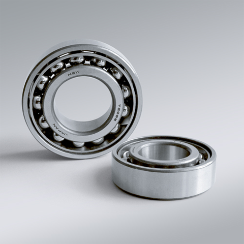
NSK NSK Angular Contact Ball Bearings ,C: Contact Angle of 15°, 7203CTYP5 ,D=17
NSK Angular Contact Ball Bearings ,C: Contact Angle of 15°, 7203CTYP5 ,D=17 Bearing Numbers Boundary Dimensions (mm) Basic Load Ratings (kN) Limiting Speeds (min-1) Factor f0 Mass (kg) approx. d D B r min. r1 min. Cr C0r Grease Oil 7203CTYP5 17 40 12 0.6 0.3 10.9 5.85 28000 38000 13.3 0.065 DESIGN, TYPES, AND FEATURES SINGLE-ROW ANGULAR CONTACT BALL BEARINGS Single-row angular contact ball bearings have a contact angle allowing them to sustain significant axial loads in one direction together with radial loads. Because of their design, when a radial load is applied, an axial force component is produced; therefore, two or more opposed bearings must be used. Since the rigidity of single-row angular contact ball bearings can be increased by preloading, they are often used in the main spindles of machine tools where high running accuracy is required (refer to Chapter 9 Preload on Page A192 for more information). Usually, the cages for angular contact ball bearings with a contact angle of 30° (designation A) or 40°(designation B) are made in accordance with Table 1, but depending on the application, machined synthetic-resin cages or molded polyamide-resin cages may also be used. The basic load ratings given in the bearing tables are based on standard cages. Though the figures in the bearing tables on Pages C086 to C101 for bearing bore diameters of 10 to 120 show bearings with single-shoulder inner rings, dual-shoulder bearings are also available. Please consult NSK for more detailed information. MATCHED ANGULAR CONTACT BALL BEARINGS The types and features of matched angular contact ball bearings are shown in Table 2. Table 2 Types and Features of Matched Angular Contact Ball Bearings Figure Arrangement Features Back-to-Back(DB)(Example)7208 A DB Radial loads and axial loads in both directions can be sustained. Since the distance between the effective load centers a0 is large, this type is suitable if moments are applied. Face-to-Face(DF)(Example)7208 B DF Radial loads and axial loads in both directions can be sustained. Compared with the DB Type, the distance between the effective load centers is small, so the capacity to sustain moments is inferior. Tandem(DT)(Example)7208 A DT Radial loads and axial loads in one direction can be sustained. Since two bearings share the axial load, this arrangement is used when the load in one direction is heavy. □Formulation of Bearing Designations Single-Row Matched Angular Contact Ball Bearings ①Bearing type 7 : Single-row angular contact ball bearings, matched angular contact ball bearings ②Dimension Series 2 : 02 Series, 3 : 03 Series, 9 : 19 Series, 0 : 10 Series ③Bore number Less than 03, Bearing bore 00 : 10mm, 01 : 12mm, 02 : 15mm, 03 : 17mmOver 04, Bearing bore Bore number ×5 (mm) ④Contact angle C : 15°, A5 : 25°, A : 30°, B : 40° ⑤Internal design EA : High Load Capacity ⑥Cage W : Pressed steel Cage, T85 : Machined brass cage (ball-guided),No designation : Machined brass cage (inner ring guided), TYN : Polyamide resin cage,T85 : Polyamide 46 resin cage, T7 : L-PPS resin cage ⑦Arrangement SU: Universal arrangement (single-row), DU : Universal arrangement (double-row),DB : Back-to-back arrangement, DF : Face-to-face arrangement, DT : Tandem arrangement ⑧Preload / Axial internal clearance EL : Extra light preload, L : Light preload, M : Medium preload, H : Heavy preloadOmitted : CN clearance, C3 : Clearance greater than CN, C4 : Clearance greater than C3,CNB : CN Clearance equivalent (universal arrangement) DOUBLE-ROW ANGULAR CONTACT BALL BEARINGS Double-row angular contact ball bearings are essentially a back- to-back mounting of two single-row angular contact ball bearings, but their inner and outer rings are each integrated into one. These bearings can sustain axial loads in both directions and offer good capacity for sustaining moment loads. They are often used as fixed- end bearings and contain cages made of pressed steel. □Formulation of Bearing Designations Double-Row Angular Contact Ball Bearings ①Bearing type 5 : Double-row angular contact ball bearings ②Dimension Series 2 : 02 Series 3: 03 Series ③Bore number 03 and under: 00 : 10mm, 01 : 12mm, 02 : 15mm, 03 : 17mm 04 and over: Bore diameter bore number ×5 (mm) ④Internal design ZZ: Steel shield on both sides, DDU: Rubber contact seal on both sides VV: Rubber noncontact seal on both sides ⑤Seals/shields Z: Steel shield on one sides, DU: Rubber contact seal on one side, V: Rubber non-contact seal on one side ⑥Grease* NS7: NS HI-LUBE
$49.46
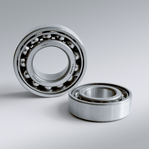
NSK NSK Angular Contact Ball Bearings ,C: Contact Angle of 15°, 7204CTYP5 ,D=20
NSK Angular Contact Ball Bearings ,C: Contact Angle of 15°, 7204CTYP5 ,D=20 Bearing Numbers Boundary Dimensions (mm) Basic Load Ratings (kN) Limiting Speeds (min-1) Factor f0 Mass (kg) approx. d D B r min. r1 min. Cr C0r Grease Oil 7204CTYP5 20 47 14 1 0.6 14.6 8.05 24000 34000 13.3 0.104 DESIGN, TYPES, AND FEATURES SINGLE-ROW ANGULAR CONTACT BALL BEARINGS Single-row angular contact ball bearings have a contact angle allowing them to sustain significant axial loads in one direction together with radial loads. Because of their design, when a radial load is applied, an axial force component is produced; therefore, two or more opposed bearings must be used. Since the rigidity of single-row angular contact ball bearings can be increased by preloading, they are often used in the main spindles of machine tools where high running accuracy is required (refer to Chapter 9 Preload on Page A192 for more information). Usually, the cages for angular contact ball bearings with a contact angle of 30° (designation A) or 40°(designation B) are made in accordance with Table 1, but depending on the application, machined synthetic-resin cages or molded polyamide-resin cages may also be used. The basic load ratings given in the bearing tables are based on standard cages. Though the figures in the bearing tables on Pages C086 to C101 for bearing bore diameters of 10 to 120 show bearings with single-shoulder inner rings, dual-shoulder bearings are also available. Please consult NSK for more detailed information. MATCHED ANGULAR CONTACT BALL BEARINGS The types and features of matched angular contact ball bearings are shown in Table 2. Table 2 Types and Features of Matched Angular Contact Ball Bearings Figure Arrangement Features Back-to-Back(DB)(Example)7208 A DB Radial loads and axial loads in both directions can be sustained. Since the distance between the effective load centers a0 is large, this type is suitable if moments are applied. Face-to-Face(DF)(Example)7208 B DF Radial loads and axial loads in both directions can be sustained. Compared with the DB Type, the distance between the effective load centers is small, so the capacity to sustain moments is inferior. Tandem(DT)(Example)7208 A DT Radial loads and axial loads in one direction can be sustained. Since two bearings share the axial load, this arrangement is used when the load in one direction is heavy. □Formulation of Bearing Designations Single-Row Matched Angular Contact Ball Bearings ①Bearing type 7 : Single-row angular contact ball bearings, matched angular contact ball bearings ②Dimension Series 2 : 02 Series, 3 : 03 Series, 9 : 19 Series, 0 : 10 Series ③Bore number Less than 03, Bearing bore 00 : 10mm, 01 : 12mm, 02 : 15mm, 03 : 17mmOver 04, Bearing bore Bore number ×5 (mm) ④Contact angle C : 15°, A5 : 25°, A : 30°, B : 40° ⑤Internal design EA : High Load Capacity ⑥Cage W : Pressed steel Cage, T85 : Machined brass cage (ball-guided),No designation : Machined brass cage (inner ring guided), TYN : Polyamide resin cage,T85 : Polyamide 46 resin cage, T7 : L-PPS resin cage ⑦Arrangement SU: Universal arrangement (single-row), DU : Universal arrangement (double-row),DB : Back-to-back arrangement, DF : Face-to-face arrangement, DT : Tandem arrangement ⑧Preload / Axial internal clearance EL : Extra light preload, L : Light preload, M : Medium preload, H : Heavy preloadOmitted : CN clearance, C3 : Clearance greater than CN, C4 : Clearance greater than C3,CNB : CN Clearance equivalent (universal arrangement) DOUBLE-ROW ANGULAR CONTACT BALL BEARINGS Double-row angular contact ball bearings are essentially a back- to-back mounting of two single-row angular contact ball bearings, but their inner and outer rings are each integrated into one. These bearings can sustain axial loads in both directions and offer good capacity for sustaining moment loads. They are often used as fixed- end bearings and contain cages made of pressed steel. □Formulation of Bearing Designations Double-Row Angular Contact Ball Bearings ①Bearing type 5 : Double-row angular contact ball bearings ②Dimension Series 2 : 02 Series 3: 03 Series ③Bore number 03 and under: 00 : 10mm, 01 : 12mm, 02 : 15mm, 03 : 17mm 04 and over: Bore diameter bore number ×5 (mm) ④Internal design ZZ: Steel shield on both sides, DDU: Rubber contact seal on both sides VV: Rubber noncontact seal on both sides ⑤Seals/shields Z: Steel shield on one sides, DU: Rubber contact seal on one side, V: Rubber non-contact seal on one side ⑥Grease* NS7: NS HI-LUBE
$51.98
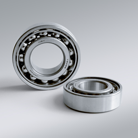
NSK NSK Angular Contact Ball Bearings ,C: Contact Angle of 15°, 7205CTYP5 ,D=25
NSK Angular Contact Ball Bearings ,C: Contact Angle of 15°, 7205CTYP5 ,D=25 Bearing Numbers Boundary Dimensions (mm) Basic Load Ratings (kN) Limiting Speeds (min-1) Factor f0 Mass (kg) approx. d D B r min. r1 min. Cr C0r Grease Oil 7205CTYP5 25 52 15 1 0.6 16.6 10.2 22000 28000 14 0.129 DESIGN, TYPES, AND FEATURES SINGLE-ROW ANGULAR CONTACT BALL BEARINGS Single-row angular contact ball bearings have a contact angle allowing them to sustain significant axial loads in one direction together with radial loads. Because of their design, when a radial load is applied, an axial force component is produced; therefore, two or more opposed bearings must be used. Since the rigidity of single-row angular contact ball bearings can be increased by preloading, they are often used in the main spindles of machine tools where high running accuracy is required (refer to Chapter 9 Preload on Page A192 for more information). Usually, the cages for angular contact ball bearings with a contact angle of 30° (designation A) or 40°(designation B) are made in accordance with Table 1, but depending on the application, machined synthetic-resin cages or molded polyamide-resin cages may also be used. The basic load ratings given in the bearing tables are based on standard cages. Though the figures in the bearing tables on Pages C086 to C101 for bearing bore diameters of 10 to 120 show bearings with single-shoulder inner rings, dual-shoulder bearings are also available. Please consult NSK for more detailed information. MATCHED ANGULAR CONTACT BALL BEARINGS The types and features of matched angular contact ball bearings are shown in Table 2. Table 2 Types and Features of Matched Angular Contact Ball Bearings Figure Arrangement Features Back-to-Back(DB)(Example)7208 A DB Radial loads and axial loads in both directions can be sustained. Since the distance between the effective load centers a0 is large, this type is suitable if moments are applied. Face-to-Face(DF)(Example)7208 B DF Radial loads and axial loads in both directions can be sustained. Compared with the DB Type, the distance between the effective load centers is small, so the capacity to sustain moments is inferior. Tandem(DT)(Example)7208 A DT Radial loads and axial loads in one direction can be sustained. Since two bearings share the axial load, this arrangement is used when the load in one direction is heavy. □Formulation of Bearing Designations Single-Row Matched Angular Contact Ball Bearings ①Bearing type 7 : Single-row angular contact ball bearings, matched angular contact ball bearings ②Dimension Series 2 : 02 Series, 3 : 03 Series, 9 : 19 Series, 0 : 10 Series ③Bore number Less than 03, Bearing bore 00 : 10mm, 01 : 12mm, 02 : 15mm, 03 : 17mmOver 04, Bearing bore Bore number ×5 (mm) ④Contact angle C : 15°, A5 : 25°, A : 30°, B : 40° ⑤Internal design EA : High Load Capacity ⑥Cage W : Pressed steel Cage, T85 : Machined brass cage (ball-guided),No designation : Machined brass cage (inner ring guided), TYN : Polyamide resin cage,T85 : Polyamide 46 resin cage, T7 : L-PPS resin cage ⑦Arrangement SU: Universal arrangement (single-row), DU : Universal arrangement (double-row),DB : Back-to-back arrangement, DF : Face-to-face arrangement, DT : Tandem arrangement ⑧Preload / Axial internal clearance EL : Extra light preload, L : Light preload, M : Medium preload, H : Heavy preloadOmitted : CN clearance, C3 : Clearance greater than CN, C4 : Clearance greater than C3,CNB : CN Clearance equivalent (universal arrangement) DOUBLE-ROW ANGULAR CONTACT BALL BEARINGS Double-row angular contact ball bearings are essentially a back- to-back mounting of two single-row angular contact ball bearings, but their inner and outer rings are each integrated into one. These bearings can sustain axial loads in both directions and offer good capacity for sustaining moment loads. They are often used as fixed- end bearings and contain cages made of pressed steel. □Formulation of Bearing Designations Double-Row Angular Contact Ball Bearings ①Bearing type 5 : Double-row angular contact ball bearings ②Dimension Series 2 : 02 Series 3: 03 Series ③Bore number 03 and under: 00 : 10mm, 01 : 12mm, 02 : 15mm, 03 : 17mm 04 and over: Bore diameter bore number ×5 (mm) ④Internal design ZZ: Steel shield on both sides, DDU: Rubber contact seal on both sides VV: Rubber noncontact seal on both sides ⑤Seals/shields Z: Steel shield on one sides, DU: Rubber contact seal on one side, V: Rubber non-contact seal on one side ⑥Grease* NS7: NS HI-LUBE
$51.98
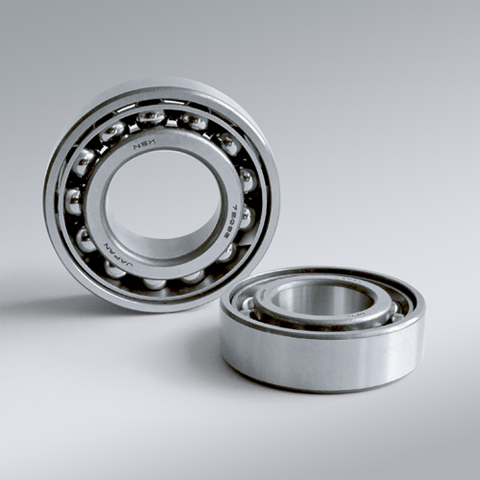
NSK NSK Angular Contact Ball Bearings ,C: Contact Angle of 15°, 7206CTYP5 ,D=30
NSK Angular Contact Ball Bearings ,C: Contact Angle of 15°, 7206CTYP5 ,D=30 Bearing Numbers Boundary Dimensions (mm) Basic Load Ratings (kN) Limiting Speeds (min-1) Factor f0 Mass (kg) approx. d D B r min. r1 min. Cr C0r Grease Oil 7206CTYP5 30 62 16 1 0.6 23 14.7 18000 24000 13.9 0.197 DESIGN, TYPES, AND FEATURES SINGLE-ROW ANGULAR CONTACT BALL BEARINGS Single-row angular contact ball bearings have a contact angle allowing them to sustain significant axial loads in one direction together with radial loads. Because of their design, when a radial load is applied, an axial force component is produced; therefore, two or more opposed bearings must be used. Since the rigidity of single-row angular contact ball bearings can be increased by preloading, they are often used in the main spindles of machine tools where high running accuracy is required (refer to Chapter 9 Preload on Page A192 for more information). Usually, the cages for angular contact ball bearings with a contact angle of 30° (designation A) or 40°(designation B) are made in accordance with Table 1, but depending on the application, machined synthetic-resin cages or molded polyamide-resin cages may also be used. The basic load ratings given in the bearing tables are based on standard cages. Though the figures in the bearing tables on Pages C086 to C101 for bearing bore diameters of 10 to 120 show bearings with single-shoulder inner rings, dual-shoulder bearings are also available. Please consult NSK for more detailed information. MATCHED ANGULAR CONTACT BALL BEARINGS The types and features of matched angular contact ball bearings are shown in Table 2. Table 2 Types and Features of Matched Angular Contact Ball Bearings Figure Arrangement Features Back-to-Back(DB)(Example)7208 A DB Radial loads and axial loads in both directions can be sustained. Since the distance between the effective load centers a0 is large, this type is suitable if moments are applied. Face-to-Face(DF)(Example)7208 B DF Radial loads and axial loads in both directions can be sustained. Compared with the DB Type, the distance between the effective load centers is small, so the capacity to sustain moments is inferior. Tandem(DT)(Example)7208 A DT Radial loads and axial loads in one direction can be sustained. Since two bearings share the axial load, this arrangement is used when the load in one direction is heavy. □Formulation of Bearing Designations Single-Row Matched Angular Contact Ball Bearings ①Bearing type 7 : Single-row angular contact ball bearings, matched angular contact ball bearings ②Dimension Series 2 : 02 Series, 3 : 03 Series, 9 : 19 Series, 0 : 10 Series ③Bore number Less than 03, Bearing bore 00 : 10mm, 01 : 12mm, 02 : 15mm, 03 : 17mmOver 04, Bearing bore Bore number ×5 (mm) ④Contact angle C : 15°, A5 : 25°, A : 30°, B : 40° ⑤Internal design EA : High Load Capacity ⑥Cage W : Pressed steel Cage, T85 : Machined brass cage (ball-guided),No designation : Machined brass cage (inner ring guided), TYN : Polyamide resin cage,T85 : Polyamide 46 resin cage, T7 : L-PPS resin cage ⑦Arrangement SU: Universal arrangement (single-row), DU : Universal arrangement (double-row),DB : Back-to-back arrangement, DF : Face-to-face arrangement, DT : Tandem arrangement ⑧Preload / Axial internal clearance EL : Extra light preload, L : Light preload, M : Medium preload, H : Heavy preloadOmitted : CN clearance, C3 : Clearance greater than CN, C4 : Clearance greater than C3,CNB : CN Clearance equivalent (universal arrangement) DOUBLE-ROW ANGULAR CONTACT BALL BEARINGS Double-row angular contact ball bearings are essentially a back- to-back mounting of two single-row angular contact ball bearings, but their inner and outer rings are each integrated into one. These bearings can sustain axial loads in both directions and offer good capacity for sustaining moment loads. They are often used as fixed- end bearings and contain cages made of pressed steel. □Formulation of Bearing Designations Double-Row Angular Contact Ball Bearings ①Bearing type 5 : Double-row angular contact ball bearings ②Dimension Series 2 : 02 Series 3: 03 Series ③Bore number 03 and under: 00 : 10mm, 01 : 12mm, 02 : 15mm, 03 : 17mm 04 and over: Bore diameter bore number ×5 (mm) ④Internal design ZZ: Steel shield on both sides, DDU: Rubber contact seal on both sides VV: Rubber noncontact seal on both sides ⑤Seals/shields Z: Steel shield on one sides, DU: Rubber contact seal on one side, V: Rubber non-contact seal on one side ⑥Grease* NS7: NS HI-LUBE
$55.79
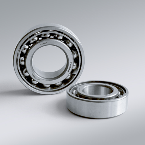
NSK NSK Angular Contact Ball Bearings ,C: Contact Angle of 15°, 7207CTYP5 ,D=35
NSK Angular Contact Ball Bearings ,C: Contact Angle of 15°, 7207CTYP5 ,D=35 Bearing Numbers Boundary Dimensions (mm) Basic Load Ratings (kN) Limiting Speeds (min-1) Factor f0 Mass (kg) approx. d D B r min. r1 min. Cr C0r Grease Oil 7207CTYP5 35 72 17 1.1 0.6 30.5 19.9 15000 20000 13.9 0.32 DESIGN, TYPES, AND FEATURES SINGLE-ROW ANGULAR CONTACT BALL BEARINGS Single-row angular contact ball bearings have a contact angle allowing them to sustain significant axial loads in one direction together with radial loads. Because of their design, when a radial load is applied, an axial force component is produced; therefore, two or more opposed bearings must be used. Since the rigidity of single-row angular contact ball bearings can be increased by preloading, they are often used in the main spindles of machine tools where high running accuracy is required (refer to Chapter 9 Preload on Page A192 for more information). Usually, the cages for angular contact ball bearings with a contact angle of 30° (designation A) or 40°(designation B) are made in accordance with Table 1, but depending on the application, machined synthetic-resin cages or molded polyamide-resin cages may also be used. The basic load ratings given in the bearing tables are based on standard cages. Though the figures in the bearing tables on Pages C086 to C101 for bearing bore diameters of 10 to 120 show bearings with single-shoulder inner rings, dual-shoulder bearings are also available. Please consult NSK for more detailed information. MATCHED ANGULAR CONTACT BALL BEARINGS The types and features of matched angular contact ball bearings are shown in Table 2. Table 2 Types and Features of Matched Angular Contact Ball Bearings Figure Arrangement Features Back-to-Back(DB)(Example)7208 A DB Radial loads and axial loads in both directions can be sustained. Since the distance between the effective load centers a0 is large, this type is suitable if moments are applied. Face-to-Face(DF)(Example)7208 B DF Radial loads and axial loads in both directions can be sustained. Compared with the DB Type, the distance between the effective load centers is small, so the capacity to sustain moments is inferior. Tandem(DT)(Example)7208 A DT Radial loads and axial loads in one direction can be sustained. Since two bearings share the axial load, this arrangement is used when the load in one direction is heavy. □Formulation of Bearing Designations Single-Row Matched Angular Contact Ball Bearings ①Bearing type 7 : Single-row angular contact ball bearings, matched angular contact ball bearings ②Dimension Series 2 : 02 Series, 3 : 03 Series, 9 : 19 Series, 0 : 10 Series ③Bore number Less than 03, Bearing bore 00 : 10mm, 01 : 12mm, 02 : 15mm, 03 : 17mmOver 04, Bearing bore Bore number ×5 (mm) ④Contact angle C : 15°, A5 : 25°, A : 30°, B : 40° ⑤Internal design EA : High Load Capacity ⑥Cage W : Pressed steel Cage, T85 : Machined brass cage (ball-guided),No designation : Machined brass cage (inner ring guided), TYN : Polyamide resin cage,T85 : Polyamide 46 resin cage, T7 : L-PPS resin cage ⑦Arrangement SU: Universal arrangement (single-row), DU : Universal arrangement (double-row),DB : Back-to-back arrangement, DF : Face-to-face arrangement, DT : Tandem arrangement ⑧Preload / Axial internal clearance EL : Extra light preload, L : Light preload, M : Medium preload, H : Heavy preloadOmitted : CN clearance, C3 : Clearance greater than CN, C4 : Clearance greater than C3,CNB : CN Clearance equivalent (universal arrangement) DOUBLE-ROW ANGULAR CONTACT BALL BEARINGS Double-row angular contact ball bearings are essentially a back- to-back mounting of two single-row angular contact ball bearings, but their inner and outer rings are each integrated into one. These bearings can sustain axial loads in both directions and offer good capacity for sustaining moment loads. They are often used as fixed- end bearings and contain cages made of pressed steel. □Formulation of Bearing Designations Double-Row Angular Contact Ball Bearings ①Bearing type 5 : Double-row angular contact ball bearings ②Dimension Series 2 : 02 Series 3: 03 Series ③Bore number 03 and under: 00 : 10mm, 01 : 12mm, 02 : 15mm, 03 : 17mm 04 and over: Bore diameter bore number ×5 (mm) ④Internal design ZZ: Steel shield on both sides, DDU: Rubber contact seal on both sides VV: Rubber noncontact seal on both sides ⑤Seals/shields Z: Steel shield on one sides, DU: Rubber contact seal on one side, V: Rubber non-contact seal on one side ⑥Grease* NS7: NS HI-LUBE
$88.74
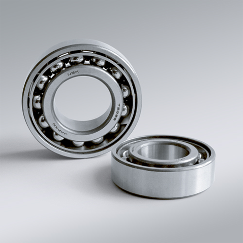
NSK NSK Angular Contact Ball Bearings ,C: Contact Angle of 15°, 7208CTYP5 ,D=40
NSK Angular Contact Ball Bearings ,C: Contact Angle of 15°, 7208CTYP5 ,D=40 Bearing Numbers Boundary Dimensions (mm) Basic Load Ratings (kN) Limiting Speeds (min-1) Factor f0 Mass (kg) approx. d D B r min. r1 min. Cr C0r Grease Oil 7208CTYP5 40 80 18 1.1 0.6 36.5 25.2 14000 19000 14.1 0.418 DESIGN, TYPES, AND FEATURES SINGLE-ROW ANGULAR CONTACT BALL BEARINGS Single-row angular contact ball bearings have a contact angle allowing them to sustain significant axial loads in one direction together with radial loads. Because of their design, when a radial load is applied, an axial force component is produced; therefore, two or more opposed bearings must be used. Since the rigidity of single-row angular contact ball bearings can be increased by preloading, they are often used in the main spindles of machine tools where high running accuracy is required (refer to Chapter 9 Preload on Page A192 for more information). Usually, the cages for angular contact ball bearings with a contact angle of 30° (designation A) or 40°(designation B) are made in accordance with Table 1, but depending on the application, machined synthetic-resin cages or molded polyamide-resin cages may also be used. The basic load ratings given in the bearing tables are based on standard cages. Though the figures in the bearing tables on Pages C086 to C101 for bearing bore diameters of 10 to 120 show bearings with single-shoulder inner rings, dual-shoulder bearings are also available. Please consult NSK for more detailed information. MATCHED ANGULAR CONTACT BALL BEARINGS The types and features of matched angular contact ball bearings are shown in Table 2. Table 2 Types and Features of Matched Angular Contact Ball Bearings Figure Arrangement Features Back-to-Back(DB)(Example)7208 A DB Radial loads and axial loads in both directions can be sustained. Since the distance between the effective load centers a0 is large, this type is suitable if moments are applied. Face-to-Face(DF)(Example)7208 B DF Radial loads and axial loads in both directions can be sustained. Compared with the DB Type, the distance between the effective load centers is small, so the capacity to sustain moments is inferior. Tandem(DT)(Example)7208 A DT Radial loads and axial loads in one direction can be sustained. Since two bearings share the axial load, this arrangement is used when the load in one direction is heavy. □Formulation of Bearing Designations Single-Row Matched Angular Contact Ball Bearings ①Bearing type 7 : Single-row angular contact ball bearings, matched angular contact ball bearings ②Dimension Series 2 : 02 Series, 3 : 03 Series, 9 : 19 Series, 0 : 10 Series ③Bore number Less than 03, Bearing bore 00 : 10mm, 01 : 12mm, 02 : 15mm, 03 : 17mmOver 04, Bearing bore Bore number ×5 (mm) ④Contact angle C : 15°, A5 : 25°, A : 30°, B : 40° ⑤Internal design EA : High Load Capacity ⑥Cage W : Pressed steel Cage, T85 : Machined brass cage (ball-guided),No designation : Machined brass cage (inner ring guided), TYN : Polyamide resin cage,T85 : Polyamide 46 resin cage, T7 : L-PPS resin cage ⑦Arrangement SU: Universal arrangement (single-row), DU : Universal arrangement (double-row),DB : Back-to-back arrangement, DF : Face-to-face arrangement, DT : Tandem arrangement ⑧Preload / Axial internal clearance EL : Extra light preload, L : Light preload, M : Medium preload, H : Heavy preloadOmitted : CN clearance, C3 : Clearance greater than CN, C4 : Clearance greater than C3,CNB : CN Clearance equivalent (universal arrangement) DOUBLE-ROW ANGULAR CONTACT BALL BEARINGS Double-row angular contact ball bearings are essentially a back- to-back mounting of two single-row angular contact ball bearings, but their inner and outer rings are each integrated into one. These bearings can sustain axial loads in both directions and offer good capacity for sustaining moment loads. They are often used as fixed- end bearings and contain cages made of pressed steel. □Formulation of Bearing Designations Double-Row Angular Contact Ball Bearings ①Bearing type 5 : Double-row angular contact ball bearings ②Dimension Series 2 : 02 Series 3: 03 Series ③Bore number 03 and under: 00 : 10mm, 01 : 12mm, 02 : 15mm, 03 : 17mm 04 and over: Bore diameter bore number ×5 (mm) ④Internal design ZZ: Steel shield on both sides, DDU: Rubber contact seal on both sides VV: Rubber noncontact seal on both sides ⑤Seals/shields Z: Steel shield on one sides, DU: Rubber contact seal on one side, V: Rubber non-contact seal on one side ⑥Grease* NS7: NS HI-LUBE
$95.09
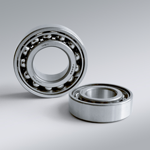
NSK NSK Angular Contact Ball Bearings ,C: Contact Angle of 15°, 7209CTYP5 ,D=45
NSK Angular Contact Ball Bearings ,C: Contact Angle of 15°, 7209CTYP5 ,D=45 Bearing Numbers Boundary Dimensions (mm) Basic Load Ratings (kN) Limiting Speeds (min-1) Factor f0 Mass (kg) approx. d D B r min. r1 min. Cr C0r Grease Oil 7209CTYP5 45 85 19 1.1 0.6 41 28.8 12000 17000 14.2 0.468 DESIGN, TYPES, AND FEATURES SINGLE-ROW ANGULAR CONTACT BALL BEARINGS Single-row angular contact ball bearings have a contact angle allowing them to sustain significant axial loads in one direction together with radial loads. Because of their design, when a radial load is applied, an axial force component is produced; therefore, two or more opposed bearings must be used. Since the rigidity of single-row angular contact ball bearings can be increased by preloading, they are often used in the main spindles of machine tools where high running accuracy is required (refer to Chapter 9 Preload on Page A192 for more information). Usually, the cages for angular contact ball bearings with a contact angle of 30° (designation A) or 40°(designation B) are made in accordance with Table 1, but depending on the application, machined synthetic-resin cages or molded polyamide-resin cages may also be used. The basic load ratings given in the bearing tables are based on standard cages. Though the figures in the bearing tables on Pages C086 to C101 for bearing bore diameters of 10 to 120 show bearings with single-shoulder inner rings, dual-shoulder bearings are also available. Please consult NSK for more detailed information. MATCHED ANGULAR CONTACT BALL BEARINGS The types and features of matched angular contact ball bearings are shown in Table 2. Table 2 Types and Features of Matched Angular Contact Ball Bearings Figure Arrangement Features Back-to-Back(DB)(Example)7208 A DB Radial loads and axial loads in both directions can be sustained. Since the distance between the effective load centers a0 is large, this type is suitable if moments are applied. Face-to-Face(DF)(Example)7208 B DF Radial loads and axial loads in both directions can be sustained. Compared with the DB Type, the distance between the effective load centers is small, so the capacity to sustain moments is inferior. Tandem(DT)(Example)7208 A DT Radial loads and axial loads in one direction can be sustained. Since two bearings share the axial load, this arrangement is used when the load in one direction is heavy. □Formulation of Bearing Designations Single-Row Matched Angular Contact Ball Bearings ①Bearing type 7 : Single-row angular contact ball bearings, matched angular contact ball bearings ②Dimension Series 2 : 02 Series, 3 : 03 Series, 9 : 19 Series, 0 : 10 Series ③Bore number Less than 03, Bearing bore 00 : 10mm, 01 : 12mm, 02 : 15mm, 03 : 17mmOver 04, Bearing bore Bore number ×5 (mm) ④Contact angle C : 15°, A5 : 25°, A : 30°, B : 40° ⑤Internal design EA : High Load Capacity ⑥Cage W : Pressed steel Cage, T85 : Machined brass cage (ball-guided),No designation : Machined brass cage (inner ring guided), TYN : Polyamide resin cage,T85 : Polyamide 46 resin cage, T7 : L-PPS resin cage ⑦Arrangement SU: Universal arrangement (single-row), DU : Universal arrangement (double-row),DB : Back-to-back arrangement, DF : Face-to-face arrangement, DT : Tandem arrangement ⑧Preload / Axial internal clearance EL : Extra light preload, L : Light preload, M : Medium preload, H : Heavy preloadOmitted : CN clearance, C3 : Clearance greater than CN, C4 : Clearance greater than C3,CNB : CN Clearance equivalent (universal arrangement) DOUBLE-ROW ANGULAR CONTACT BALL BEARINGS Double-row angular contact ball bearings are essentially a back- to-back mounting of two single-row angular contact ball bearings, but their inner and outer rings are each integrated into one. These bearings can sustain axial loads in both directions and offer good capacity for sustaining moment loads. They are often used as fixed- end bearings and contain cages made of pressed steel. □Formulation of Bearing Designations Double-Row Angular Contact Ball Bearings ①Bearing type 5 : Double-row angular contact ball bearings ②Dimension Series 2 : 02 Series 3: 03 Series ③Bore number 03 and under: 00 : 10mm, 01 : 12mm, 02 : 15mm, 03 : 17mm 04 and over: Bore diameter bore number ×5 (mm) ④Internal design ZZ: Steel shield on both sides, DDU: Rubber contact seal on both sides VV: Rubber noncontact seal on both sides ⑤Seals/shields Z: Steel shield on one sides, DU: Rubber contact seal on one side, V: Rubber non-contact seal on one side ⑥Grease* NS7: NS HI-LUBE
$107.78
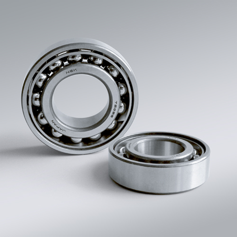
NSK NSK Angular Contact Ball Bearings ,C: Contact Angle of 15°, 7210CTYP5 ,D=50
NSK Angular Contact Ball Bearings ,C: Contact Angle of 15°, 7210CTYP5 ,D=50 Bearing Numbers Boundary Dimensions (mm) Basic Load Ratings (kN) Limiting Speeds (min-1) Factor f0 Mass (kg) approx. d D B r min. r1 min. Cr C0r Grease Oil 7210CTYP5 50 90 20 1.1 0.6 43 31.5 12000 16000 14.5 0.528 DESIGN, TYPES, AND FEATURES SINGLE-ROW ANGULAR CONTACT BALL BEARINGS Single-row angular contact ball bearings have a contact angle allowing them to sustain significant axial loads in one direction together with radial loads. Because of their design, when a radial load is applied, an axial force component is produced; therefore, two or more opposed bearings must be used. Since the rigidity of single-row angular contact ball bearings can be increased by preloading, they are often used in the main spindles of machine tools where high running accuracy is required (refer to Chapter 9 Preload on Page A192 for more information). Usually, the cages for angular contact ball bearings with a contact angle of 30° (designation A) or 40°(designation B) are made in accordance with Table 1, but depending on the application, machined synthetic-resin cages or molded polyamide-resin cages may also be used. The basic load ratings given in the bearing tables are based on standard cages. Though the figures in the bearing tables on Pages C086 to C101 for bearing bore diameters of 10 to 120 show bearings with single-shoulder inner rings, dual-shoulder bearings are also available. Please consult NSK for more detailed information. MATCHED ANGULAR CONTACT BALL BEARINGS The types and features of matched angular contact ball bearings are shown in Table 2. Table 2 Types and Features of Matched Angular Contact Ball Bearings Figure Arrangement Features Back-to-Back(DB)(Example)7208 A DB Radial loads and axial loads in both directions can be sustained. Since the distance between the effective load centers a0 is large, this type is suitable if moments are applied. Face-to-Face(DF)(Example)7208 B DF Radial loads and axial loads in both directions can be sustained. Compared with the DB Type, the distance between the effective load centers is small, so the capacity to sustain moments is inferior. Tandem(DT)(Example)7208 A DT Radial loads and axial loads in one direction can be sustained. Since two bearings share the axial load, this arrangement is used when the load in one direction is heavy. □Formulation of Bearing Designations Single-Row Matched Angular Contact Ball Bearings ①Bearing type 7 : Single-row angular contact ball bearings, matched angular contact ball bearings ②Dimension Series 2 : 02 Series, 3 : 03 Series, 9 : 19 Series, 0 : 10 Series ③Bore number Less than 03, Bearing bore 00 : 10mm, 01 : 12mm, 02 : 15mm, 03 : 17mmOver 04, Bearing bore Bore number ×5 (mm) ④Contact angle C : 15°, A5 : 25°, A : 30°, B : 40° ⑤Internal design EA : High Load Capacity ⑥Cage W : Pressed steel Cage, T85 : Machined brass cage (ball-guided),No designation : Machined brass cage (inner ring guided), TYN : Polyamide resin cage,T85 : Polyamide 46 resin cage, T7 : L-PPS resin cage ⑦Arrangement SU: Universal arrangement (single-row), DU : Universal arrangement (double-row),DB : Back-to-back arrangement, DF : Face-to-face arrangement, DT : Tandem arrangement ⑧Preload / Axial internal clearance EL : Extra light preload, L : Light preload, M : Medium preload, H : Heavy preloadOmitted : CN clearance, C3 : Clearance greater than CN, C4 : Clearance greater than C3,CNB : CN Clearance equivalent (universal arrangement) DOUBLE-ROW ANGULAR CONTACT BALL BEARINGS Double-row angular contact ball bearings are essentially a back- to-back mounting of two single-row angular contact ball bearings, but their inner and outer rings are each integrated into one. These bearings can sustain axial loads in both directions and offer good capacity for sustaining moment loads. They are often used as fixed- end bearings and contain cages made of pressed steel. □Formulation of Bearing Designations Double-Row Angular Contact Ball Bearings ①Bearing type 5 : Double-row angular contact ball bearings ②Dimension Series 2 : 02 Series 3: 03 Series ③Bore number 03 and under: 00 : 10mm, 01 : 12mm, 02 : 15mm, 03 : 17mm 04 and over: Bore diameter bore number ×5 (mm) ④Internal design ZZ: Steel shield on both sides, DDU: Rubber contact seal on both sides VV: Rubber noncontact seal on both sides ⑤Seals/shields Z: Steel shield on one sides, DU: Rubber contact seal on one side, V: Rubber non-contact seal on one side ⑥Grease* NS7: NS HI-LUBE
$123.63
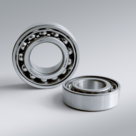
NSK NSK Angular Contact Ball Bearings ,C: Contact Angle of 15°, 7211CTYP5 ,D=55
NSK Angular Contact Ball Bearings ,C: Contact Angle of 15°, 7211CTYP5 ,D=55 Bearing Numbers Boundary Dimensions (mm) Basic Load Ratings (kN) Limiting Speeds (min-1) Factor f0 Mass (kg) approx. d D B r min. r1 min. Cr C0r Grease Oil 7211CTYP5 55 100 21 1.5 1 53 40 10000 14000 14.5 0.688 DESIGN, TYPES, AND FEATURES SINGLE-ROW ANGULAR CONTACT BALL BEARINGS Single-row angular contact ball bearings have a contact angle allowing them to sustain significant axial loads in one direction together with radial loads. Because of their design, when a radial load is applied, an axial force component is produced; therefore, two or more opposed bearings must be used. Since the rigidity of single-row angular contact ball bearings can be increased by preloading, they are often used in the main spindles of machine tools where high running accuracy is required (refer to Chapter 9 Preload on Page A192 for more information). Usually, the cages for angular contact ball bearings with a contact angle of 30° (designation A) or 40°(designation B) are made in accordance with Table 1, but depending on the application, machined synthetic-resin cages or molded polyamide-resin cages may also be used. The basic load ratings given in the bearing tables are based on standard cages. Though the figures in the bearing tables on Pages C086 to C101 for bearing bore diameters of 10 to 120 show bearings with single-shoulder inner rings, dual-shoulder bearings are also available. Please consult NSK for more detailed information. MATCHED ANGULAR CONTACT BALL BEARINGS The types and features of matched angular contact ball bearings are shown in Table 2. Table 2 Types and Features of Matched Angular Contact Ball Bearings Figure Arrangement Features Back-to-Back(DB)(Example)7208 A DB Radial loads and axial loads in both directions can be sustained. Since the distance between the effective load centers a0 is large, this type is suitable if moments are applied. Face-to-Face(DF)(Example)7208 B DF Radial loads and axial loads in both directions can be sustained. Compared with the DB Type, the distance between the effective load centers is small, so the capacity to sustain moments is inferior. Tandem(DT)(Example)7208 A DT Radial loads and axial loads in one direction can be sustained. Since two bearings share the axial load, this arrangement is used when the load in one direction is heavy. □Formulation of Bearing Designations Single-Row Matched Angular Contact Ball Bearings ①Bearing type 7 : Single-row angular contact ball bearings, matched angular contact ball bearings ②Dimension Series 2 : 02 Series, 3 : 03 Series, 9 : 19 Series, 0 : 10 Series ③Bore number Less than 03, Bearing bore 00 : 10mm, 01 : 12mm, 02 : 15mm, 03 : 17mmOver 04, Bearing bore Bore number ×5 (mm) ④Contact angle C : 15°, A5 : 25°, A : 30°, B : 40° ⑤Internal design EA : High Load Capacity ⑥Cage W : Pressed steel Cage, T85 : Machined brass cage (ball-guided),No designation : Machined brass cage (inner ring guided), TYN : Polyamide resin cage,T85 : Polyamide 46 resin cage, T7 : L-PPS resin cage ⑦Arrangement SU: Universal arrangement (single-row), DU : Universal arrangement (double-row),DB : Back-to-back arrangement, DF : Face-to-face arrangement, DT : Tandem arrangement ⑧Preload / Axial internal clearance EL : Extra light preload, L : Light preload, M : Medium preload, H : Heavy preloadOmitted : CN clearance, C3 : Clearance greater than CN, C4 : Clearance greater than C3,CNB : CN Clearance equivalent (universal arrangement) DOUBLE-ROW ANGULAR CONTACT BALL BEARINGS Double-row angular contact ball bearings are essentially a back- to-back mounting of two single-row angular contact ball bearings, but their inner and outer rings are each integrated into one. These bearings can sustain axial loads in both directions and offer good capacity for sustaining moment loads. They are often used as fixed- end bearings and contain cages made of pressed steel. □Formulation of Bearing Designations Double-Row Angular Contact Ball Bearings ①Bearing type 5 : Double-row angular contact ball bearings ②Dimension Series 2 : 02 Series 3: 03 Series ③Bore number 03 and under: 00 : 10mm, 01 : 12mm, 02 : 15mm, 03 : 17mm 04 and over: Bore diameter bore number ×5 (mm) ④Internal design ZZ: Steel shield on both sides, DDU: Rubber contact seal on both sides VV: Rubber noncontact seal on both sides ⑤Seals/shields Z: Steel shield on one sides, DU: Rubber contact seal on one side, V: Rubber non-contact seal on one side ⑥Grease* NS7: NS HI-LUBE
$146.20
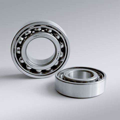
NSK NSK Angular Contact Ball Bearings ,C: Contact Angle of 15°, 7212CTYP5 ,D=60
NSK Angular Contact Ball Bearings ,C: Contact Angle of 15°, 7212CTYP5 ,D=60 Bearing Numbers Boundary Dimensions (mm) Basic Load Ratings (kN) Limiting Speeds (min-1) Factor f0 Mass (kg) approx. d D B r min. r1 min. Cr C0r Grease Oil 7212CTYP5 60 110 22 1.5 1 64 49 9500 13000 14.4 0.889 DESIGN, TYPES, AND FEATURES SINGLE-ROW ANGULAR CONTACT BALL BEARINGS Single-row angular contact ball bearings have a contact angle allowing them to sustain significant axial loads in one direction together with radial loads. Because of their design, when a radial load is applied, an axial force component is produced; therefore, two or more opposed bearings must be used. Since the rigidity of single-row angular contact ball bearings can be increased by preloading, they are often used in the main spindles of machine tools where high running accuracy is required (refer to Chapter 9 Preload on Page A192 for more information). Usually, the cages for angular contact ball bearings with a contact angle of 30° (designation A) or 40°(designation B) are made in accordance with Table 1, but depending on the application, machined synthetic-resin cages or molded polyamide-resin cages may also be used. The basic load ratings given in the bearing tables are based on standard cages. Though the figures in the bearing tables on Pages C086 to C101 for bearing bore diameters of 10 to 120 show bearings with single-shoulder inner rings, dual-shoulder bearings are also available. Please consult NSK for more detailed information. MATCHED ANGULAR CONTACT BALL BEARINGS The types and features of matched angular contact ball bearings are shown in Table 2. Table 2 Types and Features of Matched Angular Contact Ball Bearings Figure Arrangement Features Back-to-Back(DB)(Example)7208 A DB Radial loads and axial loads in both directions can be sustained. Since the distance between the effective load centers a0 is large, this type is suitable if moments are applied. Face-to-Face(DF)(Example)7208 B DF Radial loads and axial loads in both directions can be sustained. Compared with the DB Type, the distance between the effective load centers is small, so the capacity to sustain moments is inferior. Tandem(DT)(Example)7208 A DT Radial loads and axial loads in one direction can be sustained. Since two bearings share the axial load, this arrangement is used when the load in one direction is heavy. □Formulation of Bearing Designations Single-Row Matched Angular Contact Ball Bearings ①Bearing type 7 : Single-row angular contact ball bearings, matched angular contact ball bearings ②Dimension Series 2 : 02 Series, 3 : 03 Series, 9 : 19 Series, 0 : 10 Series ③Bore number Less than 03, Bearing bore 00 : 10mm, 01 : 12mm, 02 : 15mm, 03 : 17mmOver 04, Bearing bore Bore number ×5 (mm) ④Contact angle C : 15°, A5 : 25°, A : 30°, B : 40° ⑤Internal design EA : High Load Capacity ⑥Cage W : Pressed steel Cage, T85 : Machined brass cage (ball-guided),No designation : Machined brass cage (inner ring guided), TYN : Polyamide resin cage,T85 : Polyamide 46 resin cage, T7 : L-PPS resin cage ⑦Arrangement SU: Universal arrangement (single-row), DU : Universal arrangement (double-row),DB : Back-to-back arrangement, DF : Face-to-face arrangement, DT : Tandem arrangement ⑧Preload / Axial internal clearance EL : Extra light preload, L : Light preload, M : Medium preload, H : Heavy preloadOmitted : CN clearance, C3 : Clearance greater than CN, C4 : Clearance greater than C3,CNB : CN Clearance equivalent (universal arrangement) DOUBLE-ROW ANGULAR CONTACT BALL BEARINGS Double-row angular contact ball bearings are essentially a back- to-back mounting of two single-row angular contact ball bearings, but their inner and outer rings are each integrated into one. These bearings can sustain axial loads in both directions and offer good capacity for sustaining moment loads. They are often used as fixed- end bearings and contain cages made of pressed steel. □Formulation of Bearing Designations Double-Row Angular Contact Ball Bearings ①Bearing type 5 : Double-row angular contact ball bearings ②Dimension Series 2 : 02 Series 3: 03 Series ③Bore number 03 and under: 00 : 10mm, 01 : 12mm, 02 : 15mm, 03 : 17mm 04 and over: Bore diameter bore number ×5 (mm) ④Internal design ZZ: Steel shield on both sides, DDU: Rubber contact seal on both sides VV: Rubber noncontact seal on both sides ⑤Seals/shields Z: Steel shield on one sides, DU: Rubber contact seal on one side, V: Rubber non-contact seal on one side ⑥Grease* NS7: NS HI-LUBE
$169.08


