Products
Niigata Seiki Niigata Seiki (SK) SUS Feeler Gauge 0.80x1m FG-80-1
Niigata Seiki (SK) SUS Feeler Gauge 0.80x1m FG-80-1 Feature Used for assembling and adjusting automobile engines and other internal combustion engines. Cut to the required dimensions and use. Essentials for assembly and adjustment! You can cut and use only the required size. specification Size (mm): 0.80 x 1m Leaf width 12.7mm Material: Carbon tool steel (hardened) Instrumental error: (mm): ± 0.012 Case size (mm): 115 x 115 x 22 Gap measurement Body mass: 140g Package size: 115 x 115 x 22 mm 140 g
$7.81
Niigata Seiki Niigata Seiki (SK) SUS Feeler Gauge 0.90x1m FG-90-1
Niigata Seiki (SK) SUS Feeler Gauge 0.90x1m FG-90-1 Feature Used for assembling and adjusting automobile engines and other internal combustion engines. Cut to the required dimensions and use. Essentials for assembly and adjustment! You can cut and use only the required size. specification Size (mm): 0.90 x 1m Leaf width 12.7mm Material: Carbon tool steel (hardened) Instrumental error: (mm): ± 0.02 Gap measurement Body mass: 100g Package size: 1040 x 32 x 1 mm 90 g
$7.81
Niigata Seiki Niigata Seiki (SK) SUS Feeler Gauge 1.00x1m FG-00-1
Niigata Seiki (SK) SUS Feeler Gauge 1.00x1m FG-00-1 Feature Used for assembling and adjusting automobile engines and other internal combustion engines. Cut to the required dimensions and use. Essentials for assembly and adjustment! You can cut and use only the required size. specification Size (mm): 1.00 x 1m Leaf width 12.7mm Material: Carbon tool steel (hardened) Instrumental error: (mm): ± 0.02 Gap measurement Body mass: 110g Package size: 1040 x 32 x 1 mm 100 g
$7.81
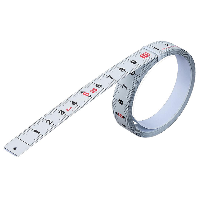
Niigata Seiki Niigata Seiki (SK) tape measure that can be pasted PM-1320KD
Niigata Seiki (SK) tape measure that can be pasted PM-1320KD Feature Abrasion resistant nylon coated tape With temporary fixing hole (2 mm) that can be temporarily fixed with nails, etc. With ready-to-use backside adhesive tape specification Material: SK material (nylon coating), maximum measurement length 2.0m, tape width 13mm, tape thickness * 0.3mm * including adhesive tape For dimensional measurement by pasting on a workbench Body mass: 32g Can be used by cutting with adhesive tape on the back Package size: 135 x 90 x 20 mm 40 g
$7.01
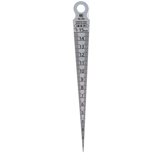
Niigata Seiki Niigata Seiki (SK) Taper gauge # 700 1-15mm TPG-700A
Niigata Seiki (SK) Taper gauge # 700 1-15mm TPG-700A Feature Silver finish You can easily measure the dimensions of grooves and gaps just by inserting them into the gaps! specification Material: Stainless hardened steel (SUS420J2) Hardness: HV480 Standard: # 7001-15 Measuring range (mm): 1 to 15 Instrumental error: (mm): ± 0.05 Scale (mm): 0.1 Taper, angle: 7 ° 9′10 ″ Measurement of grooves, gaps, hole diameters, etc. Body mass: 10g Body length: 148.5mm Body thickness: 1.2mm Package size: 56 x 5 x 205 mm 20 g
$10.65
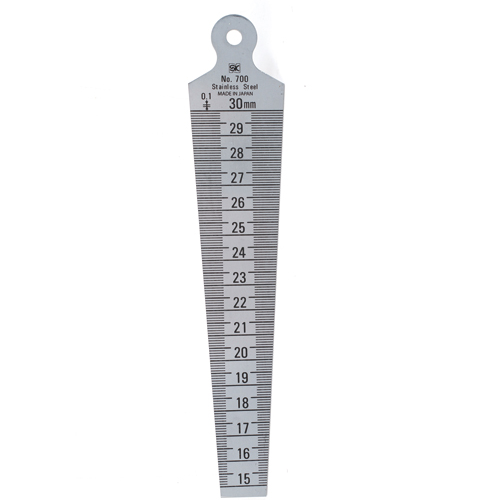
Niigata Seiki Niigata Seiki (SK) Taper gauge # 700 15-30mm TPG-700B
Niigata Seiki (SK) Taper gauge # 700 15-30mm TPG-700B Feature Silver finish You can easily measure the dimensions of grooves and gaps just by inserting them into the gaps! specification Material: Stainless hardened steel (SUS420J2) Hardness: HV480 Standard: # 7001-15 Measuring range (mm): 15 to 30 Instrumental error: (mm): ± 0.05 Scale (mm): 0.1 Taper, angle: 7 ° 9′10 ″ Measurement of grooves, gaps, hole diameters, etc. Body mass: 40g Body length: 153mm Body thickness: 1.2mm Package size: 55 x 12 x 205 mm 40 g
$18.14

Niigata Seiki Niigata Seiki (SK) Taper gauge # 700 30-45mm TPG-700C
Niigata Seiki (SK) Taper gauge # 700 30-45mm TPG-700C Feature Silver finish You can easily measure the dimensions of grooves and gaps just by inserting them into the gaps! specification Material: Stainless hardened steel (SUS420J2) Hardness: HV480 Standard: # 7001-15 Measuring range (mm): 30-45 Instrumental error: (mm): ± 0.05 Scale (mm): 0.1 Taper, angle: 7 ° 9′10 ″ Measurement of grooves, gaps, hole diameters, etc. Body mass: 60g Body length: 159mm Body thickness: 1.2mm Package size: 56 x 12 x 205 mm 60 g
$26.09

Niigata Seiki Niigata Seiki (SK) Taper gauge # 700 45-60mm TPG-700D
Niigata Seiki (SK) Taper gauge # 700 45-60mm TPG-700D Feature Silver finish You can easily measure the dimensions of grooves and gaps just by inserting them into the gaps! specification Material: Stainless hardened steel (SUS420J2) Hardness: HV480 Standard: # 7001-15 Measuring range (mm): 45-60 Instrumental error: (mm): ± 0.05 Scale (mm): 0.1 Taper, angle: 7 ° 9′10 ″ Measurement of grooves, gaps, hole diameters, etc. Body mass: 80g Body length: 161.5mm Body thickness: 1.2mm Package size: 80 x 3 x 201 mm 80 g
$34.35
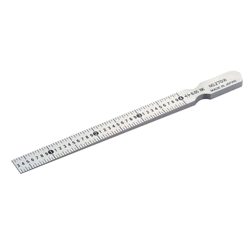
Niigata Seiki Niigata Seiki (SK) Taper gauge 0.3-4mm TPG-270A
Niigata Seiki (SK) Taper gauge 0.3-4mm TPG-270A Feature It is mainly used when measuring by inserting it into a gap. Silver finish With a PC storage case that is convenient to carry You can easily measure the dimensions of grooves and gaps just by inserting them into the gaps! specification Material: Measurement of grooves, gaps, etc. Measuring range (mm): 0.3-4 Instrumental error: (mm): ± 0.04 Scale (mm): 0.05 Taper, angle: 1 ° 54′33 ″ Measurement of grooves, gaps, etc. Body mass: 95g Body length: 160mm Body width: 11mm Package size: 23 x 188 x 15 mm 70 g
$36.08

Niigata Seiki Niigata Seiki (SK) Taper gauge 0.4-6mm TPG-270B
Niigata Seiki (SK) Taper gauge 0.4-6mm TPG-270B Feature The inner width is measured using the thickness, and it is a gauge expressed by the scale as it is. It is mainly used when measuring by inserting it into a gap. Silver finish With a PC storage case that is convenient to carry You can easily measure the dimensions of grooves and gaps just by inserting them into the gaps! specification Material: Measurement of grooves, gaps, etc. Measuring range (mm): 0.4 to 6 Instrumental error: (mm): ± 0.04 Scale (mm): 0.05 Taper, angle: 2 ° 51′45 ″ Measurement of grooves, gaps, etc. Body mass: 95g Body length: 160mm Body width: 11mm Package size: 23 x 188 x 15 mm 90 g
$45.39

Niigata Seiki Niigata Seiki (SK) Taper gauge for right angle measurement TPG-700T
Niigata Seiki (SK) Taper gauge for right angle measurement TPG-700T Feature A taper gauge dedicated to measuring the inner width. By aligning one side with the measurement surface, more stable measurement can be performed than with a normal taper gauge. Since the scale is on the side during measurement, it is possible to measure in places where the scale cannot be seen from above. specification Material: Stainless hardened steel (SUS420J2) Measuring range (mm): 1 to 15 Instrumental error: (mm): 0.1 Taper, angle: 7 ° 9′10 ″ Measurement of grooves, gaps, etc. Body mass: 10g Body length: 148.5mm Package size: 56 x 6 x 206 mm 20 g
$18.71

Niigata Seiki Niigata Seiki (SK) Taper Gauge Set TPG-267M
Niigata Seiki (SK) Taper Gauge Set TPG-267M Spec Material: Stainless quenching steel (SUS420J2) Standards : 267 M Measurement range (mm): 1 to 29 Instrumental error: (mm): ±0.05 Scale interval (mm): 0.05 Measurement of Mizo, Hole, Hole, etc. Main unit mass: 80g Main unit total length: 144mm Main unit thickness: 1.2mm Package size:45×10×180 mm 90 g
$109.39
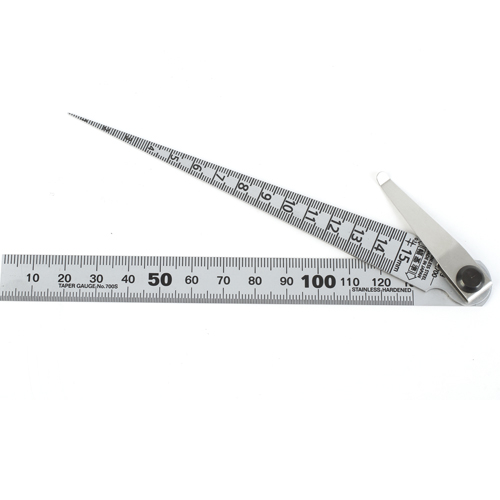
Niigata Seiki Niigata Seiki (SK) Taper gauge TPG-700S
Niigata Seiki (SK) Taper gauge TPG-700S Feature A taper gauge (# 700 1-15) and a straightedge 130 mm are set, with a clip that is convenient to carry. Silver finish A set of straightedge and feeler gauge! It is a clip type that can be stored in a pocket. specification Measurement of grooves, gaps, hole diameters, etc., length measurement Material: Stainless hardened steel (SUS420J2) Body mass: 40g Standard: 700S [Taper gauge] Measuring range (mm): 1 to 15 Instrumental error: (mm): ± 0.05 Scale (mm): 0.1 Taper angle: 7 ° 9′10 ″ Body length: 148.5mm 【Straight scale】 Measuring range (mm): 0 to 130 Instrumental error: (mm): ± 0.13 Scale (mm): 0.5 Body length: 155mm Package size: 55 x 9 x 205 mm 30 g
$19.19

Niigata Seiki Niigata Seiki (SK) Welding gauge WG-1 (M)
Niigata Seiki (SK) Welding gauge WG-1 (M) Feature For speeding up welding work and rationalizing quality control, etc. Robust, light and convenient to carry (with vinyl case) Welding essentials! It is a leg length gauge. Welding overlay, fillet, leg length, etc. can be measured in one step! specification Material: Stainless steel (SUS410) Instrumental error of fillet and surplus: ± 0.4 mm Angle measuring instrument difference (bevel angle measurement, etc.): ± 0.7 ° Gap measuring instrument difference: ± 0.4 mm Measurement of weld overlay, fillet size and angle, etc. Body mass: 79g Package size: 105 x 18 x 180 mm 110 g
$58.05

Niigata Seiki Niigata Seiki (SK) Welding Gauge WG-3
Niigata Seiki (SK) Welding Gauge WG-3 Feature For speeding up welding work and rationalizing quality control Can measure extra dimensions up to 50 mm Maintaining a sense of stability during measurement by increasing the base thickness Equipped with a rotor, various measurements are possible Silver finish reduces reflections when taking pictures With a translucent plastic case that is easy to check The latest product in the WG series! Various improvements have been made to conventional products to further improve usability. It boasts the largest extra measurement length of 50 mm (*) among existing welding gauges. (* Including other companies in leg length and throat thickness, according to our research as of July 2012) specification Material: Stainless steel (SUS410) Corner meat leg length measurement: 0 to 50 mm Throat thickness measurement of fillet: 0-50mm Extra height measurement 0-10mm * Bead straddle width: 60mm Mismatch step measurement: 0 to 50 mm * Bead straddle width: 53 mm Depth step measurement: 0 to 50 mm Plate thickness measurement: 0-35 mm Undercut depth measurement: 0 to 50 mm Bevel angle measurement: 0-60 ° C Route spacing measurement: 0.5-5 mm Measurement of weld overlay, fillet size and misalignment, gap size, undercut, angle, etc. Body mass: 198g Package size: 141 x 36 x 105 mm 290 g
$261.00

Niigata Seiki Niigata Seiki (SK) Welding gauge WG-5
Niigata Seiki (SK) Welding gauge WG-5 Feature For speeding up welding work and rationalizing quality control Can measure extra dimensions up to 50 mm Maintaining a sense of stability during measurement by increasing the base thickness Silver finish reduces reflections when taking pictures With a translucent plastic case that is easy to check The latest product in the WG series! Various improvements have been made to conventional products to further improve usability. It boasts the largest extra measurement length of 50 mm (*) among existing welding gauges. (* Including other companies in leg length and throat thickness, according to our research as of July 2012) specification Material: Stainless steel (SUS410) Corner meat leg length measurement: 0 to 50 mm Throat thickness measurement of fillet: 0-50mm Extra height measurement 0-10mm * Bead straddle width: 60mm Mismatch step measurement: 0 to 50 mm * Bead straddle width: 53 mm Depth step measurement: 0 to 50 mm Plate thickness measurement: 0 to 30 mm Measurement of weld overlay, fillet size and misalignment, etc. Body mass: 187g Package size: 141 x 36 x 105 mm 270 g
$226.46

Niigata Seiki Niigata Seiki (SK) Welding gauge WGU-2S
Niigata Seiki (SK) Welding gauge WGU-2S Welding gauge product information ■ Basic explanation Undercut depth and length can be measured easily, quickly and accurately. Since the undercut stylus is a screw type, 0 point adjustment is possible. SK welding gauges are sold online at DCM. We also handle a large number of other measuring tools and measuring instruments. ■ Product description Length accuracy: ± 0.1mm. Angle accuracy: ± 2 °. Undercut measurement range: 0 to 2 mm. Straightedge scale: 100 mm.
$105.56

Niigata Seiki Niigata Seiki (SK) Welding gauge WGU-7M
Niigata Seiki (SK) Welding gauge WGU-7M Feature Welding essentials! Welding overlay, fillet, leg length, etc. can be measured and undercut depth can be measured in one step! specification Material: Stainless steel (SUS410) Undercut depth measurement: 0 to 25 mm Bevel angle / groove angle measurement: 0-60 ° Mismatch step measurement: Bead straddle width: 42 mm Butt step measurement: 0 to 25 mm Corner meat leg length measurement and bead height control: 0 to 25 mm Fillet throat thickness measurement: 0 to 15 mm, gap measurement: 2 to 5 mm, plate thickness measurement: straightedge Measurement of weld overlay, fillet size and angle, etc. Body mass: 150g Package size: 88 x 20 x 115 mm 140 g
$66.02

Niigata Seiki Niigata Seiki (SK) Welding gauge WGU-8M
Niigata Seiki (SK) Welding gauge WGU-8M Features Made of stainless steel, it is resistant to rust and is robust. Undercut measurement is possible. Comes with a bulge measurement function after pressure welding. In compliance with the new standard notified by the Ministry of Land, Infrastructure, Transport and Tourism, a bead straddling width of 53 mm is secured by measuring the difference in level of butt welding. Use For measurement during all welding such as general welding, construction, shipbuilding, and bridges. Product specifications Specifications / standards Angle measuring instrument difference (°): ± 2 Length measuring instrument difference (mm): ± 0.6 Material Stainless steel (SUS420J2) Mass / mass unit 190g
$197.67
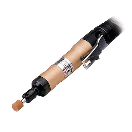
Nitto Kohki Nitto Kohki Air Sonic Axial Sander L-35C
Nitto Kohki Air Sonic Axial Sander L-35C The perfect tool for all tasks. Fast and powerful with an extremely efficient muffler and rear exhaust system. Works on all metals, wood and plastics, even very hard materials. And now that performance has been increased by the addition of an air silencer and a new rear exhaust system for grinding dust, it is even more an ideal tool for tool shops and workshops. The extraordinary performance of the muffler enables all craftsmen to work longer with less irritation from noise. For precision grinding, deburring machine parts, grinding small castings, removing welding slags, shaping and finishing wood, glass and plastic. It is a compact, easy-to-use air tool for all tasks. Sleeve Size: 6 mm Free Speed (RPM): 37.500 min-1 Air consumption (no load): 0.35 m³ / min Mass (weight): 0.45 kg (without hose) Standard accessories: 14 mm spanner: 1 pc. Wheel mounted 13 x 13 x 6 x 38: 1 pc. Sleeve PT1 / 4 x NPT 1/4: 1 pc.
$498.24
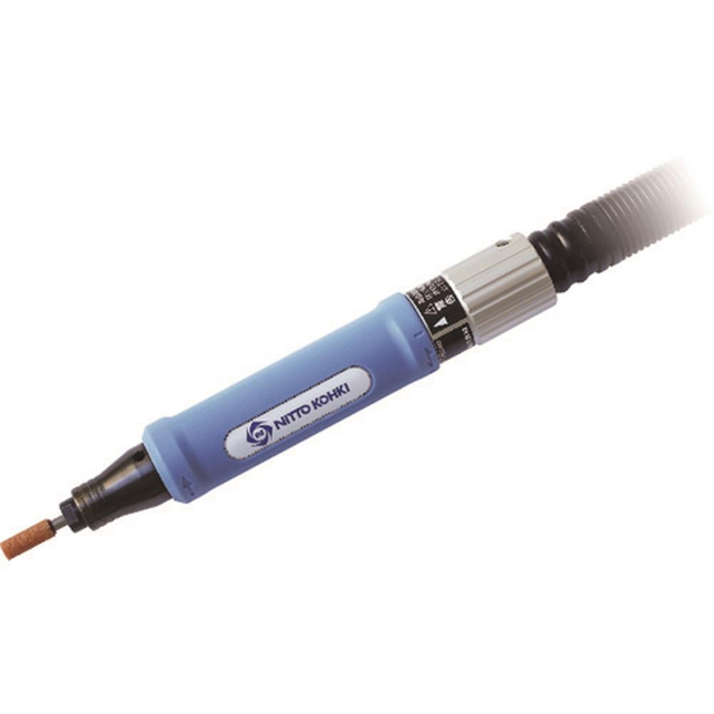
Nitto Kohki Nitto Kohki Shank Grinder AL-55A
Nitto Kohki Shank Grinder AL-55A Smooth, fast rotation and low vibration enable precise grinding, stepless speed change from 0 to 56,500 rpm meets a wide range of grinding applications, compact and lightweight for comfortable working for a long time, triangular handle adapted to the operator's hand, special plastic handle prevents cold hands and absorbs vibrations, rear exhaust system. Sleeve Size: 3 mm Free Speed (RPM): 56.500 min-1 Air consumption (no load): 0.17 m3 / min Mass (weight): 0.27 kg Standard accessories: Sleeve R1 / 4 x NPT 1/4: 1 pc. Wheel mounted 5 x 13 x 3: 1 pc. Key 7: 1 pc. Open ended spanner 7 x 9: 1 pc
$347.98
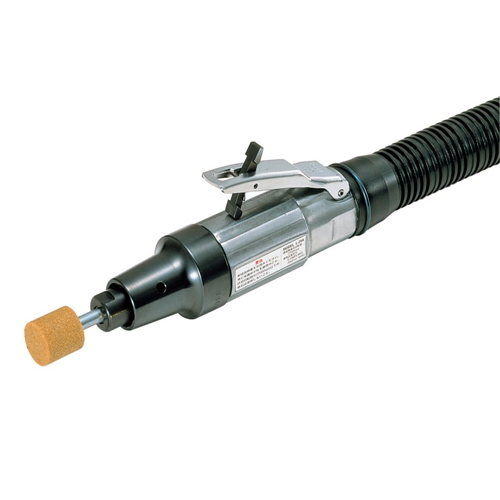
Nitto Kohki Nitto Kohki Shank Sander L-25B
Nitto Kohki Shank Sander L-25B The perfect tool for all tasks. Fast and powerful with an extremely efficient muffler and rear exhaust system. Works on all metals, wood and plastics, even very hard materials. And now that performance has been increased by the addition of an air silencer and a new rear exhaust system for grinding dust, it is even more an ideal tool for tool shops and workshops. The extraordinary performance of the muffler enables all craftsmen to work longer with less irritation from noise. For precision grinding, deburring machine parts, grinding small castings, removing welding slags, shaping and finishing wood, glass and plastic. It is a compact, easy-to-use air tool for all tasks. Sleeve Size: 6 mm Free Speed (RPM): 27,000 min-1 Air consumption (no load): 0.4 m³ / min Mass (weight): 0.6 kg (without hose) Standard accessories: 14 mm spanner: 1 pc. Mounted wheel no.2: 1 pc. Installed wheel no.3: 1 pc. Block pin: 1 pc. Sleeve PT1 / 4 x NPT 1/4: 1 pc.
$386.39
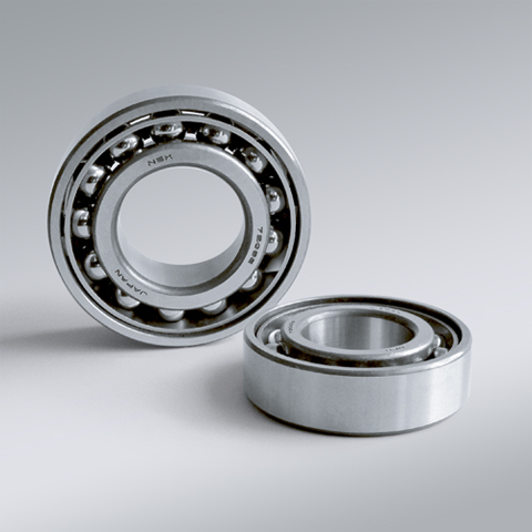
NSK NSK Angular Contact Ball Bearings ,A :Contact Angle of 30°, 7218AW ,D=90
NSK Angular Contact Ball Bearings ,A :Contact Angle of 30°, 7218AW ,D=90 Bearing Numbers Boundary Dimensions (mm) Basic Load Ratings (kN) Limiting Speeds (min-1) Factor f0 Mass (kg) approx. d D B r min. r1 min. Cr C0r Grease Oil 7218AW 90 160 30 2 1 118 103 3600 4800 ?€ 2.25 DESIGN, TYPES, AND FEATURES SINGLE-ROW ANGULAR CONTACT BALL BEARINGS Single-row angular contact ball bearings have a contact angle allowing them to sustain significant axial loads in one direction together with radial loads. Because of their design, when a radial load is applied, an axial force component is produced; therefore, two or more opposed bearings must be used. Since the rigidity of single-row angular contact ball bearings can be increased by preloading, they are often used in the main spindles of machine tools where high running accuracy is required (refer to Chapter 9 Preload on Page A192 for more information). Usually, the cages for angular contact ball bearings with a contact angle of 30° (designation A) or 40°(designation B) are made in accordance with Table 1, but depending on the application, machined synthetic-resin cages or molded polyamide-resin cages may also be used. The basic load ratings given in the bearing tables are based on standard cages. Though the figures in the bearing tables on Pages C086 to C101 for bearing bore diameters of 10 to 120 show bearings with single-shoulder inner rings, dual-shoulder bearings are also available. Please consult NSK for more detailed information. MATCHED ANGULAR CONTACT BALL BEARINGS The types and features of matched angular contact ball bearings are shown in Table 2. Table 2 Types and Features of Matched Angular Contact Ball Bearings Figure Arrangement Features Back-to-Back(DB)(Example)7208 A DB Radial loads and axial loads in both directions can be sustained. Since the distance between the effective load centers a0 is large, this type is suitable if moments are applied. Face-to-Face(DF)(Example)7208 B DF Radial loads and axial loads in both directions can be sustained. Compared with the DB Type, the distance between the effective load centers is small, so the capacity to sustain moments is inferior. Tandem(DT)(Example)7208 A DT Radial loads and axial loads in one direction can be sustained. Since two bearings share the axial load, this arrangement is used when the load in one direction is heavy. ?¡Formulation of Bearing Designations Single-Row Matched Angular Contact Ball Bearings ? Bearing type 7 : Single-row angular contact ball bearings, matched angular contact ball bearings ?¡Dimension Series 2 : 02 Series, 3 : 03 Series, 9 : 19 Series, 0 : 10 Series ?¢Bore number Less than 03, Bearing bore 00 : 10mm, 01 : 12mm, 02 : 15mm, 03 : 17mmOver 04, Bearing bore Bore number ×5 (mm) ?£Contact angle C : 15°, A5 : 25°, A : 30°, B : 40° ?¤Internal design EA : High Load Capacity ?¥Cage W : Pressed steel Cage, T85 : Machined brass cage (ball-guided),No designation : Machined brass cage (inner ring guided), TYN : Polyamide resin cage,T85 : Polyamide 46 resin cage, T7 : L-PPS resin cage ?¦Arrangement SU: Universal arrangement (single-row), DU : Universal arrangement (double-row),DB : Back-to-back arrangement, DF : Face-to-face arrangement, DT : Tandem arrangement ?§Preload / Axial internal clearance EL : Extra light preload, L : Light preload, M : Medium preload, H : Heavy preloadOmitted : CN clearance, C3 : Clearance greater than CN, C4 : Clearance greater than C3,CNB : CN Clearance equivalent (universal arrangement) DOUBLE-ROW ANGULAR CONTACT BALL BEARINGS Double-row angular contact ball bearings are essentially a back- to-back mounting of two single-row angular contact ball bearings, but their inner and outer rings are each integrated into one. These bearings can sustain axial loads in both directions and offer good capacity for sustaining moment loads. They are often used as fixed- end bearings and contain cages made of pressed steel. ?¡Formulation of Bearing Designations Double-Row Angular Contact Ball Bearings ? Bearing type 5 : Double-row angular contact ball bearings ?¡Dimension Series 2 : 02 Series 3: 03 Series ?¢Bore number 03 and under: 00 : 10mm, 01 : 12mm, 02 : 15mm, 03 : 17mm 04 and over: Bore diameter bore number ×5 (mm) ?£Internal design ZZ: Steel shield on both sides, DDU: Rubber contact seal on both sides VV: Rubber noncontact seal on both sides ?¤Seals/shields Z: Steel shield on one sides, DU: Rubber contact seal on one side, V: Rubber non-contact seal on one side ?¥Grease* NS7: NS HI-LUBE
$166.58
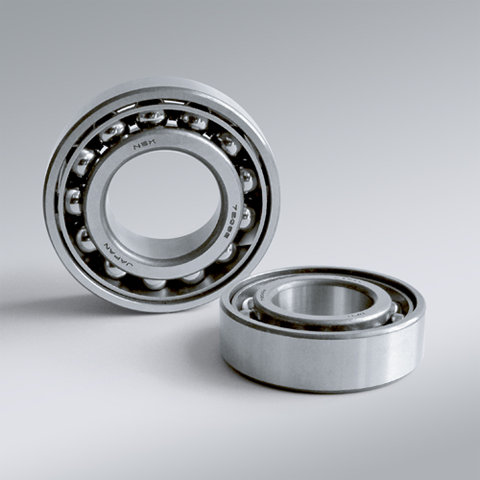
NSK NSK Angular Contact Ball Bearings ,A :Contact Angle of 30°, 7219AW ,D=95
NSK Angular Contact Ball Bearings ,A :Contact Angle of 30°, 7219AW ,D=95 Bearing Numbers Boundary Dimensions (mm) Basic Load Ratings (kN) Limiting Speeds (min-1) Factor f0 Mass (kg) approx. d D B r min. r1 min. Cr C0r Grease Oil 7219AW 95 170 32 2.1 1.1 128 111 3400 4500 ?€ 2.68 DESIGN, TYPES, AND FEATURES SINGLE-ROW ANGULAR CONTACT BALL BEARINGS Single-row angular contact ball bearings have a contact angle allowing them to sustain significant axial loads in one direction together with radial loads. Because of their design, when a radial load is applied, an axial force component is produced; therefore, two or more opposed bearings must be used. Since the rigidity of single-row angular contact ball bearings can be increased by preloading, they are often used in the main spindles of machine tools where high running accuracy is required (refer to Chapter 9 Preload on Page A192 for more information). Usually, the cages for angular contact ball bearings with a contact angle of 30° (designation A) or 40°(designation B) are made in accordance with Table 1, but depending on the application, machined synthetic-resin cages or molded polyamide-resin cages may also be used. The basic load ratings given in the bearing tables are based on standard cages. Though the figures in the bearing tables on Pages C086 to C101 for bearing bore diameters of 10 to 120 show bearings with single-shoulder inner rings, dual-shoulder bearings are also available. Please consult NSK for more detailed information. MATCHED ANGULAR CONTACT BALL BEARINGS The types and features of matched angular contact ball bearings are shown in Table 2. Table 2 Types and Features of Matched Angular Contact Ball Bearings Figure Arrangement Features Back-to-Back(DB)(Example)7208 A DB Radial loads and axial loads in both directions can be sustained. Since the distance between the effective load centers a0 is large, this type is suitable if moments are applied. Face-to-Face(DF)(Example)7208 B DF Radial loads and axial loads in both directions can be sustained. Compared with the DB Type, the distance between the effective load centers is small, so the capacity to sustain moments is inferior. Tandem(DT)(Example)7208 A DT Radial loads and axial loads in one direction can be sustained. Since two bearings share the axial load, this arrangement is used when the load in one direction is heavy. ?¡Formulation of Bearing Designations Single-Row Matched Angular Contact Ball Bearings ? Bearing type 7 : Single-row angular contact ball bearings, matched angular contact ball bearings ?¡Dimension Series 2 : 02 Series, 3 : 03 Series, 9 : 19 Series, 0 : 10 Series ?¢Bore number Less than 03, Bearing bore 00 : 10mm, 01 : 12mm, 02 : 15mm, 03 : 17mmOver 04, Bearing bore Bore number ×5 (mm) ?£Contact angle C : 15°, A5 : 25°, A : 30°, B : 40° ?¤Internal design EA : High Load Capacity ?¥Cage W : Pressed steel Cage, T85 : Machined brass cage (ball-guided),No designation : Machined brass cage (inner ring guided), TYN : Polyamide resin cage,T85 : Polyamide 46 resin cage, T7 : L-PPS resin cage ?¦Arrangement SU: Universal arrangement (single-row), DU : Universal arrangement (double-row),DB : Back-to-back arrangement, DF : Face-to-face arrangement, DT : Tandem arrangement ?§Preload / Axial internal clearance EL : Extra light preload, L : Light preload, M : Medium preload, H : Heavy preloadOmitted : CN clearance, C3 : Clearance greater than CN, C4 : Clearance greater than C3,CNB : CN Clearance equivalent (universal arrangement) DOUBLE-ROW ANGULAR CONTACT BALL BEARINGS Double-row angular contact ball bearings are essentially a back- to-back mounting of two single-row angular contact ball bearings, but their inner and outer rings are each integrated into one. These bearings can sustain axial loads in both directions and offer good capacity for sustaining moment loads. They are often used as fixed- end bearings and contain cages made of pressed steel. ?¡Formulation of Bearing Designations Double-Row Angular Contact Ball Bearings ? Bearing type 5 : Double-row angular contact ball bearings ?¡Dimension Series 2 : 02 Series 3: 03 Series ?¢Bore number 03 and under: 00 : 10mm, 01 : 12mm, 02 : 15mm, 03 : 17mm 04 and over: Bore diameter bore number ×5 (mm) ?£Internal design ZZ: Steel shield on both sides, DDU: Rubber contact seal on both sides VV: Rubber noncontact seal on both sides ?¤Seals/shields Z: Steel shield on one sides, DU: Rubber contact seal on one side, V: Rubber non-contact seal on one side ?¥Grease* NS7: NS HI-LUBE
$187.92
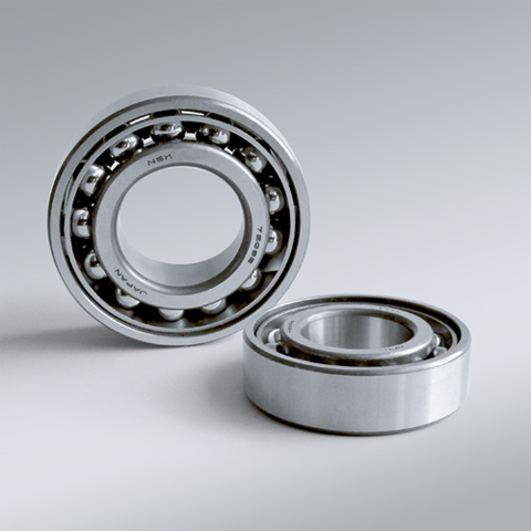
NSK NSK Angular Contact Ball Bearings ,A :Contact Angle of 30°, 7220AW ,D=100
NSK Angular Contact Ball Bearings ,A :Contact Angle of 30°, 7220AW ,D=100 Bearing Numbers Boundary Dimensions (mm) Basic Load Ratings (kN) Limiting Speeds (min-1) Factor f0 Mass (kg) approx. d D B r min. r1 min. Cr C0r Grease Oil 7220AW 100 180 34 2.1 1.1 144 126 3200 4300 ?€ 3.22 DESIGN, TYPES, AND FEATURES SINGLE-ROW ANGULAR CONTACT BALL BEARINGS Single-row angular contact ball bearings have a contact angle allowing them to sustain significant axial loads in one direction together with radial loads. Because of their design, when a radial load is applied, an axial force component is produced; therefore, two or more opposed bearings must be used. Since the rigidity of single-row angular contact ball bearings can be increased by preloading, they are often used in the main spindles of machine tools where high running accuracy is required (refer to Chapter 9 Preload on Page A192 for more information). Usually, the cages for angular contact ball bearings with a contact angle of 30° (designation A) or 40°(designation B) are made in accordance with Table 1, but depending on the application, machined synthetic-resin cages or molded polyamide-resin cages may also be used. The basic load ratings given in the bearing tables are based on standard cages. Though the figures in the bearing tables on Pages C086 to C101 for bearing bore diameters of 10 to 120 show bearings with single-shoulder inner rings, dual-shoulder bearings are also available. Please consult NSK for more detailed information. MATCHED ANGULAR CONTACT BALL BEARINGS The types and features of matched angular contact ball bearings are shown in Table 2. Table 2 Types and Features of Matched Angular Contact Ball Bearings Figure Arrangement Features Back-to-Back(DB)(Example)7208 A DB Radial loads and axial loads in both directions can be sustained. Since the distance between the effective load centers a0 is large, this type is suitable if moments are applied. Face-to-Face(DF)(Example)7208 B DF Radial loads and axial loads in both directions can be sustained. Compared with the DB Type, the distance between the effective load centers is small, so the capacity to sustain moments is inferior. Tandem(DT)(Example)7208 A DT Radial loads and axial loads in one direction can be sustained. Since two bearings share the axial load, this arrangement is used when the load in one direction is heavy. ?¡Formulation of Bearing Designations Single-Row Matched Angular Contact Ball Bearings ? Bearing type 7 : Single-row angular contact ball bearings, matched angular contact ball bearings ?¡Dimension Series 2 : 02 Series, 3 : 03 Series, 9 : 19 Series, 0 : 10 Series ?¢Bore number Less than 03, Bearing bore 00 : 10mm, 01 : 12mm, 02 : 15mm, 03 : 17mmOver 04, Bearing bore Bore number ×5 (mm) ?£Contact angle C : 15°, A5 : 25°, A : 30°, B : 40° ?¤Internal design EA : High Load Capacity ?¥Cage W : Pressed steel Cage, T85 : Machined brass cage (ball-guided),No designation : Machined brass cage (inner ring guided), TYN : Polyamide resin cage,T85 : Polyamide 46 resin cage, T7 : L-PPS resin cage ?¦Arrangement SU: Universal arrangement (single-row), DU : Universal arrangement (double-row),DB : Back-to-back arrangement, DF : Face-to-face arrangement, DT : Tandem arrangement ?§Preload / Axial internal clearance EL : Extra light preload, L : Light preload, M : Medium preload, H : Heavy preloadOmitted : CN clearance, C3 : Clearance greater than CN, C4 : Clearance greater than C3,CNB : CN Clearance equivalent (universal arrangement) DOUBLE-ROW ANGULAR CONTACT BALL BEARINGS Double-row angular contact ball bearings are essentially a back- to-back mounting of two single-row angular contact ball bearings, but their inner and outer rings are each integrated into one. These bearings can sustain axial loads in both directions and offer good capacity for sustaining moment loads. They are often used as fixed- end bearings and contain cages made of pressed steel. ?¡Formulation of Bearing Designations Double-Row Angular Contact Ball Bearings ? Bearing type 5 : Double-row angular contact ball bearings ?¡Dimension Series 2 : 02 Series 3: 03 Series ?¢Bore number 03 and under: 00 : 10mm, 01 : 12mm, 02 : 15mm, 03 : 17mm 04 and over: Bore diameter bore number ×5 (mm) ?£Internal design ZZ: Steel shield on both sides, DDU: Rubber contact seal on both sides VV: Rubber noncontact seal on both sides ?¤Seals/shields Z: Steel shield on one sides, DU: Rubber contact seal on one side, V: Rubber non-contact seal on one side ?¥Grease* NS7: NS HI-LUBE
$216.44
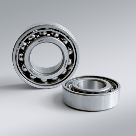
NSK NSK Angular Contact Ball Bearings ,A :Contact Angle of 30°, 7221A ,D=105
NSK Angular Contact Ball Bearings ,A :Contact Angle of 30°, 7221A ,D=105 Bearing Numbers Boundary Dimensions (mm) Basic Load Ratings (kN) Limiting Speeds (min-1) Factor f0 Mass (kg) approx. d D B r min. r1 min. Cr C0r Grease Oil 7221A 105 190 36 2.1 1.1 157 142 3000 4000 ?€ 3.84 DESIGN, TYPES, AND FEATURES SINGLE-ROW ANGULAR CONTACT BALL BEARINGS Single-row angular contact ball bearings have a contact angle allowing them to sustain significant axial loads in one direction together with radial loads. Because of their design, when a radial load is applied, an axial force component is produced; therefore, two or more opposed bearings must be used. Since the rigidity of single-row angular contact ball bearings can be increased by preloading, they are often used in the main spindles of machine tools where high running accuracy is required (refer to Chapter 9 Preload on Page A192 for more information). Usually, the cages for angular contact ball bearings with a contact angle of 30° (designation A) or 40°(designation B) are made in accordance with Table 1, but depending on the application, machined synthetic-resin cages or molded polyamide-resin cages may also be used. The basic load ratings given in the bearing tables are based on standard cages. Though the figures in the bearing tables on Pages C086 to C101 for bearing bore diameters of 10 to 120 show bearings with single-shoulder inner rings, dual-shoulder bearings are also available. Please consult NSK for more detailed information. MATCHED ANGULAR CONTACT BALL BEARINGS The types and features of matched angular contact ball bearings are shown in Table 2. Table 2 Types and Features of Matched Angular Contact Ball Bearings Figure Arrangement Features Back-to-Back(DB)(Example)7208 A DB Radial loads and axial loads in both directions can be sustained. Since the distance between the effective load centers a0 is large, this type is suitable if moments are applied. Face-to-Face(DF)(Example)7208 B DF Radial loads and axial loads in both directions can be sustained. Compared with the DB Type, the distance between the effective load centers is small, so the capacity to sustain moments is inferior. Tandem(DT)(Example)7208 A DT Radial loads and axial loads in one direction can be sustained. Since two bearings share the axial load, this arrangement is used when the load in one direction is heavy. ?¡Formulation of Bearing Designations Single-Row Matched Angular Contact Ball Bearings ? Bearing type 7 : Single-row angular contact ball bearings, matched angular contact ball bearings ?¡Dimension Series 2 : 02 Series, 3 : 03 Series, 9 : 19 Series, 0 : 10 Series ?¢Bore number Less than 03, Bearing bore 00 : 10mm, 01 : 12mm, 02 : 15mm, 03 : 17mmOver 04, Bearing bore Bore number ×5 (mm) ?£Contact angle C : 15°, A5 : 25°, A : 30°, B : 40° ?¤Internal design EA : High Load Capacity ?¥Cage W : Pressed steel Cage, T85 : Machined brass cage (ball-guided),No designation : Machined brass cage (inner ring guided), TYN : Polyamide resin cage,T85 : Polyamide 46 resin cage, T7 : L-PPS resin cage ?¦Arrangement SU: Universal arrangement (single-row), DU : Universal arrangement (double-row),DB : Back-to-back arrangement, DF : Face-to-face arrangement, DT : Tandem arrangement ?§Preload / Axial internal clearance EL : Extra light preload, L : Light preload, M : Medium preload, H : Heavy preloadOmitted : CN clearance, C3 : Clearance greater than CN, C4 : Clearance greater than C3,CNB : CN Clearance equivalent (universal arrangement) DOUBLE-ROW ANGULAR CONTACT BALL BEARINGS Double-row angular contact ball bearings are essentially a back- to-back mounting of two single-row angular contact ball bearings, but their inner and outer rings are each integrated into one. These bearings can sustain axial loads in both directions and offer good capacity for sustaining moment loads. They are often used as fixed- end bearings and contain cages made of pressed steel. ?¡Formulation of Bearing Designations Double-Row Angular Contact Ball Bearings ? Bearing type 5 : Double-row angular contact ball bearings ?¡Dimension Series 2 : 02 Series 3: 03 Series ?¢Bore number 03 and under: 00 : 10mm, 01 : 12mm, 02 : 15mm, 03 : 17mm 04 and over: Bore diameter bore number ×5 (mm) ?£Internal design ZZ: Steel shield on both sides, DDU: Rubber contact seal on both sides VV: Rubber noncontact seal on both sides ?¤Seals/shields Z: Steel shield on one sides, DU: Rubber contact seal on one side, V: Rubber non-contact seal on one side ?¥Grease* NS7: NS HI-LUBE
$412.48

NSK NSK Angular Contact Ball Bearings ,A :Contact Angle of 30°, 7222A ,D=110
NSK Angular Contact Ball Bearings ,A :Contact Angle of 30°, 7222A ,D=110 Bearing Numbers Boundary Dimensions (mm) Basic Load Ratings (kN) Limiting Speeds (min-1) Factor f0 Mass (kg) approx. d D B r min. r1 min. Cr C0r Grease Oil 7222A 110 200 38 2.1 1.1 170 158 2800 3800 ?€ 4.49 DESIGN, TYPES, AND FEATURES SINGLE-ROW ANGULAR CONTACT BALL BEARINGS Single-row angular contact ball bearings have a contact angle allowing them to sustain significant axial loads in one direction together with radial loads. Because of their design, when a radial load is applied, an axial force component is produced; therefore, two or more opposed bearings must be used. Since the rigidity of single-row angular contact ball bearings can be increased by preloading, they are often used in the main spindles of machine tools where high running accuracy is required (refer to Chapter 9 Preload on Page A192 for more information). Usually, the cages for angular contact ball bearings with a contact angle of 30° (designation A) or 40°(designation B) are made in accordance with Table 1, but depending on the application, machined synthetic-resin cages or molded polyamide-resin cages may also be used. The basic load ratings given in the bearing tables are based on standard cages. Though the figures in the bearing tables on Pages C086 to C101 for bearing bore diameters of 10 to 120 show bearings with single-shoulder inner rings, dual-shoulder bearings are also available. Please consult NSK for more detailed information. MATCHED ANGULAR CONTACT BALL BEARINGS The types and features of matched angular contact ball bearings are shown in Table 2. Table 2 Types and Features of Matched Angular Contact Ball Bearings Figure Arrangement Features Back-to-Back(DB)(Example)7208 A DB Radial loads and axial loads in both directions can be sustained. Since the distance between the effective load centers a0 is large, this type is suitable if moments are applied. Face-to-Face(DF)(Example)7208 B DF Radial loads and axial loads in both directions can be sustained. Compared with the DB Type, the distance between the effective load centers is small, so the capacity to sustain moments is inferior. Tandem(DT)(Example)7208 A DT Radial loads and axial loads in one direction can be sustained. Since two bearings share the axial load, this arrangement is used when the load in one direction is heavy. ?¡Formulation of Bearing Designations Single-Row Matched Angular Contact Ball Bearings ? Bearing type 7 : Single-row angular contact ball bearings, matched angular contact ball bearings ?¡Dimension Series 2 : 02 Series, 3 : 03 Series, 9 : 19 Series, 0 : 10 Series ?¢Bore number Less than 03, Bearing bore 00 : 10mm, 01 : 12mm, 02 : 15mm, 03 : 17mmOver 04, Bearing bore Bore number ×5 (mm) ?£Contact angle C : 15°, A5 : 25°, A : 30°, B : 40° ?¤Internal design EA : High Load Capacity ?¥Cage W : Pressed steel Cage, T85 : Machined brass cage (ball-guided),No designation : Machined brass cage (inner ring guided), TYN : Polyamide resin cage,T85 : Polyamide 46 resin cage, T7 : L-PPS resin cage ?¦Arrangement SU: Universal arrangement (single-row), DU : Universal arrangement (double-row),DB : Back-to-back arrangement, DF : Face-to-face arrangement, DT : Tandem arrangement ?§Preload / Axial internal clearance EL : Extra light preload, L : Light preload, M : Medium preload, H : Heavy preloadOmitted : CN clearance, C3 : Clearance greater than CN, C4 : Clearance greater than C3,CNB : CN Clearance equivalent (universal arrangement) DOUBLE-ROW ANGULAR CONTACT BALL BEARINGS Double-row angular contact ball bearings are essentially a back- to-back mounting of two single-row angular contact ball bearings, but their inner and outer rings are each integrated into one. These bearings can sustain axial loads in both directions and offer good capacity for sustaining moment loads. They are often used as fixed- end bearings and contain cages made of pressed steel. ?¡Formulation of Bearing Designations Double-Row Angular Contact Ball Bearings ? Bearing type 5 : Double-row angular contact ball bearings ?¡Dimension Series 2 : 02 Series 3: 03 Series ?¢Bore number 03 and under: 00 : 10mm, 01 : 12mm, 02 : 15mm, 03 : 17mm 04 and over: Bore diameter bore number ×5 (mm) ?£Internal design ZZ: Steel shield on both sides, DDU: Rubber contact seal on both sides VV: Rubber noncontact seal on both sides ?¤Seals/shields Z: Steel shield on one sides, DU: Rubber contact seal on one side, V: Rubber non-contact seal on one side ?¥Grease* NS7: NS HI-LUBE
$484.88
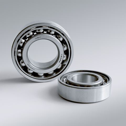
NSK NSK Angular Contact Ball Bearings ,A :Contact Angle of 30°, 7224A ,D=120
NSK Angular Contact Ball Bearings ,A :Contact Angle of 30°, 7224A ,D=120 Bearing Numbers Boundary Dimensions (mm) Basic Load Ratings (kN) Limiting Speeds (min-1) Factor f0 Mass (kg) approx. d D B r min. r1 min. Cr C0r Grease Oil 7224A 120 215 40 2.1 1.1 183 177 3200 4500 ?€ 6.22 DESIGN, TYPES, AND FEATURES SINGLE-ROW ANGULAR CONTACT BALL BEARINGS Single-row angular contact ball bearings have a contact angle allowing them to sustain significant axial loads in one direction together with radial loads. Because of their design, when a radial load is applied, an axial force component is produced; therefore, two or more opposed bearings must be used. Since the rigidity of single-row angular contact ball bearings can be increased by preloading, they are often used in the main spindles of machine tools where high running accuracy is required (refer to Chapter 9 Preload on Page A192 for more information). Usually, the cages for angular contact ball bearings with a contact angle of 30° (designation A) or 40°(designation B) are made in accordance with Table 1, but depending on the application, machined synthetic-resin cages or molded polyamide-resin cages may also be used. The basic load ratings given in the bearing tables are based on standard cages. Though the figures in the bearing tables on Pages C086 to C101 for bearing bore diameters of 10 to 120 show bearings with single-shoulder inner rings, dual-shoulder bearings are also available. Please consult NSK for more detailed information. MATCHED ANGULAR CONTACT BALL BEARINGS The types and features of matched angular contact ball bearings are shown in Table 2. Table 2 Types and Features of Matched Angular Contact Ball Bearings Figure Arrangement Features Back-to-Back(DB)(Example)7208 A DB Radial loads and axial loads in both directions can be sustained. Since the distance between the effective load centers a0 is large, this type is suitable if moments are applied. Face-to-Face(DF)(Example)7208 B DF Radial loads and axial loads in both directions can be sustained. Compared with the DB Type, the distance between the effective load centers is small, so the capacity to sustain moments is inferior. Tandem(DT)(Example)7208 A DT Radial loads and axial loads in one direction can be sustained. Since two bearings share the axial load, this arrangement is used when the load in one direction is heavy. ?¡Formulation of Bearing Designations Single-Row Matched Angular Contact Ball Bearings ? Bearing type 7 : Single-row angular contact ball bearings, matched angular contact ball bearings ?¡Dimension Series 2 : 02 Series, 3 : 03 Series, 9 : 19 Series, 0 : 10 Series ?¢Bore number Less than 03, Bearing bore 00 : 10mm, 01 : 12mm, 02 : 15mm, 03 : 17mmOver 04, Bearing bore Bore number ×5 (mm) ?£Contact angle C : 15°, A5 : 25°, A : 30°, B : 40° ?¤Internal design EA : High Load Capacity ?¥Cage W : Pressed steel Cage, T85 : Machined brass cage (ball-guided),No designation : Machined brass cage (inner ring guided), TYN : Polyamide resin cage,T85 : Polyamide 46 resin cage, T7 : L-PPS resin cage ?¦Arrangement SU: Universal arrangement (single-row), DU : Universal arrangement (double-row),DB : Back-to-back arrangement, DF : Face-to-face arrangement, DT : Tandem arrangement ?§Preload / Axial internal clearance EL : Extra light preload, L : Light preload, M : Medium preload, H : Heavy preloadOmitted : CN clearance, C3 : Clearance greater than CN, C4 : Clearance greater than C3,CNB : CN Clearance equivalent (universal arrangement) DOUBLE-ROW ANGULAR CONTACT BALL BEARINGS Double-row angular contact ball bearings are essentially a back- to-back mounting of two single-row angular contact ball bearings, but their inner and outer rings are each integrated into one. These bearings can sustain axial loads in both directions and offer good capacity for sustaining moment loads. They are often used as fixed- end bearings and contain cages made of pressed steel. ?¡Formulation of Bearing Designations Double-Row Angular Contact Ball Bearings ? Bearing type 5 : Double-row angular contact ball bearings ?¡Dimension Series 2 : 02 Series 3: 03 Series ?¢Bore number 03 and under: 00 : 10mm, 01 : 12mm, 02 : 15mm, 03 : 17mm 04 and over: Bore diameter bore number ×5 (mm) ?£Internal design ZZ: Steel shield on both sides, DDU: Rubber contact seal on both sides VV: Rubber noncontact seal on both sides ?¤Seals/shields Z: Steel shield on one sides, DU: Rubber contact seal on one side, V: Rubber non-contact seal on one side ?¥Grease* NS7: NS HI-LUBE
$690.98
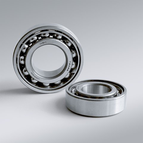
NSK NSK Angular Contact Ball Bearings ,A :Contact Angle of 30°, 7226A ,D=130
NSK Angular Contact Ball Bearings ,A :Contact Angle of 30°, 7226A ,D=130 Bearing Numbers Boundary Dimensions (mm) Basic Load Ratings (kN) Limiting Speeds (min-1) Factor f0 Mass (kg) approx. d D B r min. r1 min. Cr C0r Grease Oil 7226A 130 230 40 3 1.1 189 193 2400 3200 ?€ 7.06 DESIGN, TYPES, AND FEATURES SINGLE-ROW ANGULAR CONTACT BALL BEARINGS Single-row angular contact ball bearings have a contact angle allowing them to sustain significant axial loads in one direction together with radial loads. Because of their design, when a radial load is applied, an axial force component is produced; therefore, two or more opposed bearings must be used. Since the rigidity of single-row angular contact ball bearings can be increased by preloading, they are often used in the main spindles of machine tools where high running accuracy is required (refer to Chapter 9 Preload on Page A192 for more information). Usually, the cages for angular contact ball bearings with a contact angle of 30° (designation A) or 40°(designation B) are made in accordance with Table 1, but depending on the application, machined synthetic-resin cages or molded polyamide-resin cages may also be used. The basic load ratings given in the bearing tables are based on standard cages. Though the figures in the bearing tables on Pages C086 to C101 for bearing bore diameters of 10 to 120 show bearings with single-shoulder inner rings, dual-shoulder bearings are also available. Please consult NSK for more detailed information. MATCHED ANGULAR CONTACT BALL BEARINGS The types and features of matched angular contact ball bearings are shown in Table 2. Table 2 Types and Features of Matched Angular Contact Ball Bearings Figure Arrangement Features Back-to-Back(DB)(Example)7208 A DB Radial loads and axial loads in both directions can be sustained. Since the distance between the effective load centers a0 is large, this type is suitable if moments are applied. Face-to-Face(DF)(Example)7208 B DF Radial loads and axial loads in both directions can be sustained. Compared with the DB Type, the distance between the effective load centers is small, so the capacity to sustain moments is inferior. Tandem(DT)(Example)7208 A DT Radial loads and axial loads in one direction can be sustained. Since two bearings share the axial load, this arrangement is used when the load in one direction is heavy. ?¡Formulation of Bearing Designations Single-Row Matched Angular Contact Ball Bearings ? Bearing type 7 : Single-row angular contact ball bearings, matched angular contact ball bearings ?¡Dimension Series 2 : 02 Series, 3 : 03 Series, 9 : 19 Series, 0 : 10 Series ?¢Bore number Less than 03, Bearing bore 00 : 10mm, 01 : 12mm, 02 : 15mm, 03 : 17mmOver 04, Bearing bore Bore number ×5 (mm) ?£Contact angle C : 15°, A5 : 25°, A : 30°, B : 40° ?¤Internal design EA : High Load Capacity ?¥Cage W : Pressed steel Cage, T85 : Machined brass cage (ball-guided),No designation : Machined brass cage (inner ring guided), TYN : Polyamide resin cage,T85 : Polyamide 46 resin cage, T7 : L-PPS resin cage ?¦Arrangement SU: Universal arrangement (single-row), DU : Universal arrangement (double-row),DB : Back-to-back arrangement, DF : Face-to-face arrangement, DT : Tandem arrangement ?§Preload / Axial internal clearance EL : Extra light preload, L : Light preload, M : Medium preload, H : Heavy preloadOmitted : CN clearance, C3 : Clearance greater than CN, C4 : Clearance greater than C3,CNB : CN Clearance equivalent (universal arrangement) DOUBLE-ROW ANGULAR CONTACT BALL BEARINGS Double-row angular contact ball bearings are essentially a back- to-back mounting of two single-row angular contact ball bearings, but their inner and outer rings are each integrated into one. These bearings can sustain axial loads in both directions and offer good capacity for sustaining moment loads. They are often used as fixed- end bearings and contain cages made of pressed steel. ?¡Formulation of Bearing Designations Double-Row Angular Contact Ball Bearings ? Bearing type 5 : Double-row angular contact ball bearings ?¡Dimension Series 2 : 02 Series 3: 03 Series ?¢Bore number 03 and under: 00 : 10mm, 01 : 12mm, 02 : 15mm, 03 : 17mm 04 and over: Bore diameter bore number ×5 (mm) ?£Internal design ZZ: Steel shield on both sides, DDU: Rubber contact seal on both sides VV: Rubber noncontact seal on both sides ?¤Seals/shields Z: Steel shield on one sides, DU: Rubber contact seal on one side, V: Rubber non-contact seal on one side ?¥Grease* NS7: NS HI-LUBE
$869.48
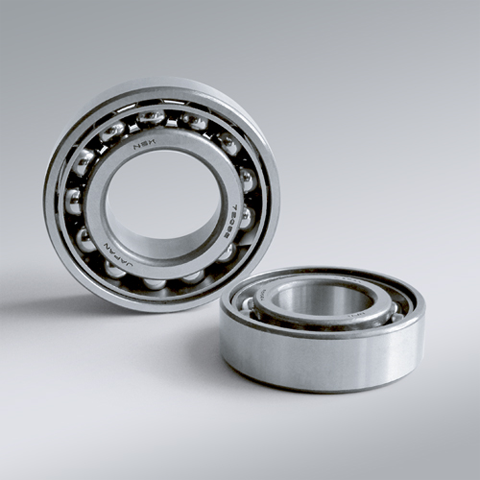
NSK NSK Angular Contact Ball Bearings ,A :Contact Angle of 30°, 7228A ,D=140
NSK Angular Contact Ball Bearings ,A :Contact Angle of 30°, 7228A ,D=140 Bearing Numbers Boundary Dimensions (mm) Basic Load Ratings (kN) Limiting Speeds (min-1) Factor f0 Mass (kg) approx. d D B r min. r1 min. Cr C0r Grease Oil 7228A 140 250 42 3 1.1 218 234 2200 3000 ?€ 8.92 DESIGN, TYPES, AND FEATURES SINGLE-ROW ANGULAR CONTACT BALL BEARINGS Single-row angular contact ball bearings have a contact angle allowing them to sustain significant axial loads in one direction together with radial loads. Because of their design, when a radial load is applied, an axial force component is produced; therefore, two or more opposed bearings must be used. Since the rigidity of single-row angular contact ball bearings can be increased by preloading, they are often used in the main spindles of machine tools where high running accuracy is required (refer to Chapter 9 Preload on Page A192 for more information). Usually, the cages for angular contact ball bearings with a contact angle of 30° (designation A) or 40°(designation B) are made in accordance with Table 1, but depending on the application, machined synthetic-resin cages or molded polyamide-resin cages may also be used. The basic load ratings given in the bearing tables are based on standard cages. Though the figures in the bearing tables on Pages C086 to C101 for bearing bore diameters of 10 to 120 show bearings with single-shoulder inner rings, dual-shoulder bearings are also available. Please consult NSK for more detailed information. MATCHED ANGULAR CONTACT BALL BEARINGS The types and features of matched angular contact ball bearings are shown in Table 2. Table 2 Types and Features of Matched Angular Contact Ball Bearings Figure Arrangement Features Back-to-Back(DB)(Example)7208 A DB Radial loads and axial loads in both directions can be sustained. Since the distance between the effective load centers a0 is large, this type is suitable if moments are applied. Face-to-Face(DF)(Example)7208 B DF Radial loads and axial loads in both directions can be sustained. Compared with the DB Type, the distance between the effective load centers is small, so the capacity to sustain moments is inferior. Tandem(DT)(Example)7208 A DT Radial loads and axial loads in one direction can be sustained. Since two bearings share the axial load, this arrangement is used when the load in one direction is heavy. ?¡Formulation of Bearing Designations Single-Row Matched Angular Contact Ball Bearings ? Bearing type 7 : Single-row angular contact ball bearings, matched angular contact ball bearings ?¡Dimension Series 2 : 02 Series, 3 : 03 Series, 9 : 19 Series, 0 : 10 Series ?¢Bore number Less than 03, Bearing bore 00 : 10mm, 01 : 12mm, 02 : 15mm, 03 : 17mmOver 04, Bearing bore Bore number ×5 (mm) ?£Contact angle C : 15°, A5 : 25°, A : 30°, B : 40° ?¤Internal design EA : High Load Capacity ?¥Cage W : Pressed steel Cage, T85 : Machined brass cage (ball-guided),No designation : Machined brass cage (inner ring guided), TYN : Polyamide resin cage,T85 : Polyamide 46 resin cage, T7 : L-PPS resin cage ?¦Arrangement SU: Universal arrangement (single-row), DU : Universal arrangement (double-row),DB : Back-to-back arrangement, DF : Face-to-face arrangement, DT : Tandem arrangement ?§Preload / Axial internal clearance EL : Extra light preload, L : Light preload, M : Medium preload, H : Heavy preloadOmitted : CN clearance, C3 : Clearance greater than CN, C4 : Clearance greater than C3,CNB : CN Clearance equivalent (universal arrangement) DOUBLE-ROW ANGULAR CONTACT BALL BEARINGS Double-row angular contact ball bearings are essentially a back- to-back mounting of two single-row angular contact ball bearings, but their inner and outer rings are each integrated into one. These bearings can sustain axial loads in both directions and offer good capacity for sustaining moment loads. They are often used as fixed- end bearings and contain cages made of pressed steel. ?¡Formulation of Bearing Designations Double-Row Angular Contact Ball Bearings ? Bearing type 5 : Double-row angular contact ball bearings ?¡Dimension Series 2 : 02 Series 3: 03 Series ?¢Bore number 03 and under: 00 : 10mm, 01 : 12mm, 02 : 15mm, 03 : 17mm 04 and over: Bore diameter bore number ×5 (mm) ?£Internal design ZZ: Steel shield on both sides, DDU: Rubber contact seal on both sides VV: Rubber noncontact seal on both sides ?¤Seals/shields Z: Steel shield on one sides, DU: Rubber contact seal on one side, V: Rubber non-contact seal on one side ?¥Grease* NS7: NS HI-LUBE
$959.82
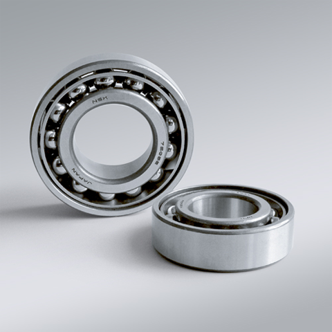
NSK NSK Angular Contact Ball Bearings ,A :Contact Angle of 30°, 7230A ,D=150
NSK Angular Contact Ball Bearings ,A :Contact Angle of 30°, 7230A ,D=150 Bearing Numbers Boundary Dimensions (mm) Basic Load Ratings (kN) Limiting Speeds (min-1) Factor f0 Mass (kg) approx. d D B r min. r1 min. Cr C0r Grease Oil 7230A 150 270 45 3 1.1 248 280 2000 2800 ?€ 11.2 DESIGN, TYPES, AND FEATURES SINGLE-ROW ANGULAR CONTACT BALL BEARINGS Single-row angular contact ball bearings have a contact angle allowing them to sustain significant axial loads in one direction together with radial loads. Because of their design, when a radial load is applied, an axial force component is produced; therefore, two or more opposed bearings must be used. Since the rigidity of single-row angular contact ball bearings can be increased by preloading, they are often used in the main spindles of machine tools where high running accuracy is required (refer to Chapter 9 Preload on Page A192 for more information). Usually, the cages for angular contact ball bearings with a contact angle of 30° (designation A) or 40°(designation B) are made in accordance with Table 1, but depending on the application, machined synthetic-resin cages or molded polyamide-resin cages may also be used. The basic load ratings given in the bearing tables are based on standard cages. Though the figures in the bearing tables on Pages C086 to C101 for bearing bore diameters of 10 to 120 show bearings with single-shoulder inner rings, dual-shoulder bearings are also available. Please consult NSK for more detailed information. MATCHED ANGULAR CONTACT BALL BEARINGS The types and features of matched angular contact ball bearings are shown in Table 2. Table 2 Types and Features of Matched Angular Contact Ball Bearings Figure Arrangement Features Back-to-Back(DB)(Example)7208 A DB Radial loads and axial loads in both directions can be sustained. Since the distance between the effective load centers a0 is large, this type is suitable if moments are applied. Face-to-Face(DF)(Example)7208 B DF Radial loads and axial loads in both directions can be sustained. Compared with the DB Type, the distance between the effective load centers is small, so the capacity to sustain moments is inferior. Tandem(DT)(Example)7208 A DT Radial loads and axial loads in one direction can be sustained. Since two bearings share the axial load, this arrangement is used when the load in one direction is heavy. ?¡Formulation of Bearing Designations Single-Row Matched Angular Contact Ball Bearings ? Bearing type 7 : Single-row angular contact ball bearings, matched angular contact ball bearings ?¡Dimension Series 2 : 02 Series, 3 : 03 Series, 9 : 19 Series, 0 : 10 Series ?¢Bore number Less than 03, Bearing bore 00 : 10mm, 01 : 12mm, 02 : 15mm, 03 : 17mmOver 04, Bearing bore Bore number ×5 (mm) ?£Contact angle C : 15°, A5 : 25°, A : 30°, B : 40° ?¤Internal design EA : High Load Capacity ?¥Cage W : Pressed steel Cage, T85 : Machined brass cage (ball-guided),No designation : Machined brass cage (inner ring guided), TYN : Polyamide resin cage,T85 : Polyamide 46 resin cage, T7 : L-PPS resin cage ?¦Arrangement SU: Universal arrangement (single-row), DU : Universal arrangement (double-row),DB : Back-to-back arrangement, DF : Face-to-face arrangement, DT : Tandem arrangement ?§Preload / Axial internal clearance EL : Extra light preload, L : Light preload, M : Medium preload, H : Heavy preloadOmitted : CN clearance, C3 : Clearance greater than CN, C4 : Clearance greater than C3,CNB : CN Clearance equivalent (universal arrangement) DOUBLE-ROW ANGULAR CONTACT BALL BEARINGS Double-row angular contact ball bearings are essentially a back- to-back mounting of two single-row angular contact ball bearings, but their inner and outer rings are each integrated into one. These bearings can sustain axial loads in both directions and offer good capacity for sustaining moment loads. They are often used as fixed- end bearings and contain cages made of pressed steel. ?¡Formulation of Bearing Designations Double-Row Angular Contact Ball Bearings ? Bearing type 5 : Double-row angular contact ball bearings ?¡Dimension Series 2 : 02 Series 3: 03 Series ?¢Bore number 03 and under: 00 : 10mm, 01 : 12mm, 02 : 15mm, 03 : 17mm 04 and over: Bore diameter bore number ×5 (mm) ?£Internal design ZZ: Steel shield on both sides, DDU: Rubber contact seal on both sides VV: Rubber noncontact seal on both sides ?¤Seals/shields Z: Steel shield on one sides, DU: Rubber contact seal on one side, V: Rubber non-contact seal on one side ?¥Grease* NS7: NS HI-LUBE
$1,383.86
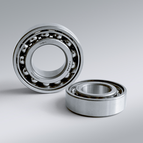
NSK NSK Angular Contact Ball Bearings ,A :Contact Angle of 30°, 7232A ,D=160
NSK Angular Contact Ball Bearings ,A :Contact Angle of 30°, 7232A ,D=160 Bearing Numbers Boundary Dimensions (mm) Basic Load Ratings (kN) Limiting Speeds (min-1) Factor f0 Mass (kg) approx. d D B r min. r1 min. Cr C0r Grease Oil 7232A 160 290 48 3 1.1 263 305 1900 2600 ?€ 14.1 DESIGN, TYPES, AND FEATURES SINGLE-ROW ANGULAR CONTACT BALL BEARINGS Single-row angular contact ball bearings have a contact angle allowing them to sustain significant axial loads in one direction together with radial loads. Because of their design, when a radial load is applied, an axial force component is produced; therefore, two or more opposed bearings must be used. Since the rigidity of single-row angular contact ball bearings can be increased by preloading, they are often used in the main spindles of machine tools where high running accuracy is required (refer to Chapter 9 Preload on Page A192 for more information). Usually, the cages for angular contact ball bearings with a contact angle of 30° (designation A) or 40°(designation B) are made in accordance with Table 1, but depending on the application, machined synthetic-resin cages or molded polyamide-resin cages may also be used. The basic load ratings given in the bearing tables are based on standard cages. Though the figures in the bearing tables on Pages C086 to C101 for bearing bore diameters of 10 to 120 show bearings with single-shoulder inner rings, dual-shoulder bearings are also available. Please consult NSK for more detailed information. MATCHED ANGULAR CONTACT BALL BEARINGS The types and features of matched angular contact ball bearings are shown in Table 2. Table 2 Types and Features of Matched Angular Contact Ball Bearings Figure Arrangement Features Back-to-Back(DB)(Example)7208 A DB Radial loads and axial loads in both directions can be sustained. Since the distance between the effective load centers a0 is large, this type is suitable if moments are applied. Face-to-Face(DF)(Example)7208 B DF Radial loads and axial loads in both directions can be sustained. Compared with the DB Type, the distance between the effective load centers is small, so the capacity to sustain moments is inferior. Tandem(DT)(Example)7208 A DT Radial loads and axial loads in one direction can be sustained. Since two bearings share the axial load, this arrangement is used when the load in one direction is heavy. ?¡Formulation of Bearing Designations Single-Row Matched Angular Contact Ball Bearings ? Bearing type 7 : Single-row angular contact ball bearings, matched angular contact ball bearings ?¡Dimension Series 2 : 02 Series, 3 : 03 Series, 9 : 19 Series, 0 : 10 Series ?¢Bore number Less than 03, Bearing bore 00 : 10mm, 01 : 12mm, 02 : 15mm, 03 : 17mmOver 04, Bearing bore Bore number ×5 (mm) ?£Contact angle C : 15°, A5 : 25°, A : 30°, B : 40° ?¤Internal design EA : High Load Capacity ?¥Cage W : Pressed steel Cage, T85 : Machined brass cage (ball-guided),No designation : Machined brass cage (inner ring guided), TYN : Polyamide resin cage,T85 : Polyamide 46 resin cage, T7 : L-PPS resin cage ?¦Arrangement SU: Universal arrangement (single-row), DU : Universal arrangement (double-row),DB : Back-to-back arrangement, DF : Face-to-face arrangement, DT : Tandem arrangement ?§Preload / Axial internal clearance EL : Extra light preload, L : Light preload, M : Medium preload, H : Heavy preloadOmitted : CN clearance, C3 : Clearance greater than CN, C4 : Clearance greater than C3,CNB : CN Clearance equivalent (universal arrangement) DOUBLE-ROW ANGULAR CONTACT BALL BEARINGS Double-row angular contact ball bearings are essentially a back- to-back mounting of two single-row angular contact ball bearings, but their inner and outer rings are each integrated into one. These bearings can sustain axial loads in both directions and offer good capacity for sustaining moment loads. They are often used as fixed- end bearings and contain cages made of pressed steel. ?¡Formulation of Bearing Designations Double-Row Angular Contact Ball Bearings ? Bearing type 5 : Double-row angular contact ball bearings ?¡Dimension Series 2 : 02 Series 3: 03 Series ?¢Bore number 03 and under: 00 : 10mm, 01 : 12mm, 02 : 15mm, 03 : 17mm 04 and over: Bore diameter bore number ×5 (mm) ?£Internal design ZZ: Steel shield on both sides, DDU: Rubber contact seal on both sides VV: Rubber noncontact seal on both sides ?¤Seals/shields Z: Steel shield on one sides, DU: Rubber contact seal on one side, V: Rubber non-contact seal on one side ?¥Grease* NS7: NS HI-LUBE
$1,465.60
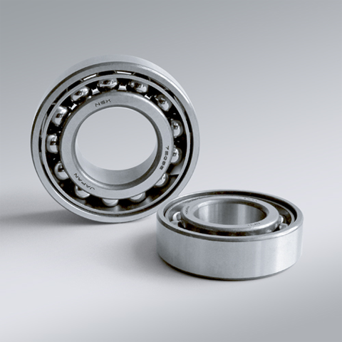
NSK NSK Angular Contact Ball Bearings ,A :Contact Angle of 30°, 7300AW ,D=10
NSK Angular Contact Ball Bearings ,A :Contact Angle of 30°, 7300AW ,D=10 Bearing Numbers Boundary Dimensions (mm) Basic Load Ratings (kN) Limiting Speeds (min-1) Factor f0 Mass (kg) approx. d D B r min. r1 min. Cr C0r Grease Oil 7300AW 10 35 11 0.6 0.3 9.3 4.3 16000 22000 ?€ 0.053 DESIGN, TYPES, AND FEATURES SINGLE-ROW ANGULAR CONTACT BALL BEARINGS Single-row angular contact ball bearings have a contact angle allowing them to sustain significant axial loads in one direction together with radial loads. Because of their design, when a radial load is applied, an axial force component is produced; therefore, two or more opposed bearings must be used. Since the rigidity of single-row angular contact ball bearings can be increased by preloading, they are often used in the main spindles of machine tools where high running accuracy is required (refer to Chapter 9 Preload on Page A192 for more information). Usually, the cages for angular contact ball bearings with a contact angle of 30° (designation A) or 40°(designation B) are made in accordance with Table 1, but depending on the application, machined synthetic-resin cages or molded polyamide-resin cages may also be used. The basic load ratings given in the bearing tables are based on standard cages. Though the figures in the bearing tables on Pages C086 to C101 for bearing bore diameters of 10 to 120 show bearings with single-shoulder inner rings, dual-shoulder bearings are also available. Please consult NSK for more detailed information. MATCHED ANGULAR CONTACT BALL BEARINGS The types and features of matched angular contact ball bearings are shown in Table 2. Table 2 Types and Features of Matched Angular Contact Ball Bearings Figure Arrangement Features Back-to-Back(DB)(Example)7208 A DB Radial loads and axial loads in both directions can be sustained. Since the distance between the effective load centers a0 is large, this type is suitable if moments are applied. Face-to-Face(DF)(Example)7208 B DF Radial loads and axial loads in both directions can be sustained. Compared with the DB Type, the distance between the effective load centers is small, so the capacity to sustain moments is inferior. Tandem(DT)(Example)7208 A DT Radial loads and axial loads in one direction can be sustained. Since two bearings share the axial load, this arrangement is used when the load in one direction is heavy. ?¡Formulation of Bearing Designations Single-Row Matched Angular Contact Ball Bearings ? Bearing type 7 : Single-row angular contact ball bearings, matched angular contact ball bearings ?¡Dimension Series 2 : 02 Series, 3 : 03 Series, 9 : 19 Series, 0 : 10 Series ?¢Bore number Less than 03, Bearing bore 00 : 10mm, 01 : 12mm, 02 : 15mm, 03 : 17mmOver 04, Bearing bore Bore number ×5 (mm) ?£Contact angle C : 15°, A5 : 25°, A : 30°, B : 40° ?¤Internal design EA : High Load Capacity ?¥Cage W : Pressed steel Cage, T85 : Machined brass cage (ball-guided),No designation : Machined brass cage (inner ring guided), TYN : Polyamide resin cage,T85 : Polyamide 46 resin cage, T7 : L-PPS resin cage ?¦Arrangement SU: Universal arrangement (single-row), DU : Universal arrangement (double-row),DB : Back-to-back arrangement, DF : Face-to-face arrangement, DT : Tandem arrangement ?§Preload / Axial internal clearance EL : Extra light preload, L : Light preload, M : Medium preload, H : Heavy preloadOmitted : CN clearance, C3 : Clearance greater than CN, C4 : Clearance greater than C3,CNB : CN Clearance equivalent (universal arrangement) DOUBLE-ROW ANGULAR CONTACT BALL BEARINGS Double-row angular contact ball bearings are essentially a back- to-back mounting of two single-row angular contact ball bearings, but their inner and outer rings are each integrated into one. These bearings can sustain axial loads in both directions and offer good capacity for sustaining moment loads. They are often used as fixed- end bearings and contain cages made of pressed steel. ?¡Formulation of Bearing Designations Double-Row Angular Contact Ball Bearings ? Bearing type 5 : Double-row angular contact ball bearings ?¡Dimension Series 2 : 02 Series 3: 03 Series ?¢Bore number 03 and under: 00 : 10mm, 01 : 12mm, 02 : 15mm, 03 : 17mm 04 and over: Bore diameter bore number ×5 (mm) ?£Internal design ZZ: Steel shield on both sides, DDU: Rubber contact seal on both sides VV: Rubber noncontact seal on both sides ?¤Seals/shields Z: Steel shield on one sides, DU: Rubber contact seal on one side, V: Rubber non-contact seal on one side ?¥Grease* NS7: NS HI-LUBE
$16.25
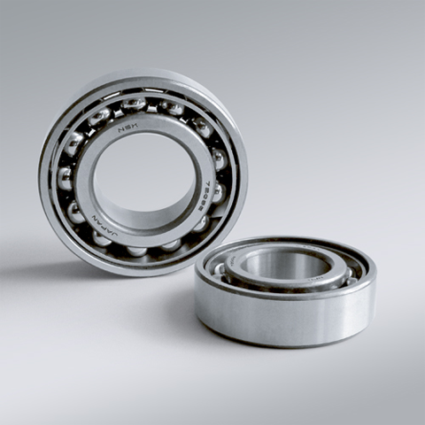
NSK NSK Angular Contact Ball Bearings ,A :Contact Angle of 30°, 7301AW ,D=12
NSK Angular Contact Ball Bearings ,A :Contact Angle of 30°, 7301AW ,D=12 Bearing Numbers Boundary Dimensions (mm) Basic Load Ratings (kN) Limiting Speeds (min-1) Factor f0 Mass (kg) approx. d D B r min. r1 min. Cr C0r Grease Oil 7301AW 12 37 12 1 0.6 9.45 4.5 15000 20000 ?€ 0.06 DESIGN, TYPES, AND FEATURES SINGLE-ROW ANGULAR CONTACT BALL BEARINGS Single-row angular contact ball bearings have a contact angle allowing them to sustain significant axial loads in one direction together with radial loads. Because of their design, when a radial load is applied, an axial force component is produced; therefore, two or more opposed bearings must be used. Since the rigidity of single-row angular contact ball bearings can be increased by preloading, they are often used in the main spindles of machine tools where high running accuracy is required (refer to Chapter 9 Preload on Page A192 for more information). Usually, the cages for angular contact ball bearings with a contact angle of 30° (designation A) or 40°(designation B) are made in accordance with Table 1, but depending on the application, machined synthetic-resin cages or molded polyamide-resin cages may also be used. The basic load ratings given in the bearing tables are based on standard cages. Though the figures in the bearing tables on Pages C086 to C101 for bearing bore diameters of 10 to 120 show bearings with single-shoulder inner rings, dual-shoulder bearings are also available. Please consult NSK for more detailed information. MATCHED ANGULAR CONTACT BALL BEARINGS The types and features of matched angular contact ball bearings are shown in Table 2. Table 2 Types and Features of Matched Angular Contact Ball Bearings Figure Arrangement Features Back-to-Back(DB)(Example)7208 A DB Radial loads and axial loads in both directions can be sustained. Since the distance between the effective load centers a0 is large, this type is suitable if moments are applied. Face-to-Face(DF)(Example)7208 B DF Radial loads and axial loads in both directions can be sustained. Compared with the DB Type, the distance between the effective load centers is small, so the capacity to sustain moments is inferior. Tandem(DT)(Example)7208 A DT Radial loads and axial loads in one direction can be sustained. Since two bearings share the axial load, this arrangement is used when the load in one direction is heavy. ?¡Formulation of Bearing Designations Single-Row Matched Angular Contact Ball Bearings ? Bearing type 7 : Single-row angular contact ball bearings, matched angular contact ball bearings ?¡Dimension Series 2 : 02 Series, 3 : 03 Series, 9 : 19 Series, 0 : 10 Series ?¢Bore number Less than 03, Bearing bore 00 : 10mm, 01 : 12mm, 02 : 15mm, 03 : 17mmOver 04, Bearing bore Bore number ×5 (mm) ?£Contact angle C : 15°, A5 : 25°, A : 30°, B : 40° ?¤Internal design EA : High Load Capacity ?¥Cage W : Pressed steel Cage, T85 : Machined brass cage (ball-guided),No designation : Machined brass cage (inner ring guided), TYN : Polyamide resin cage,T85 : Polyamide 46 resin cage, T7 : L-PPS resin cage ?¦Arrangement SU: Universal arrangement (single-row), DU : Universal arrangement (double-row),DB : Back-to-back arrangement, DF : Face-to-face arrangement, DT : Tandem arrangement ?§Preload / Axial internal clearance EL : Extra light preload, L : Light preload, M : Medium preload, H : Heavy preloadOmitted : CN clearance, C3 : Clearance greater than CN, C4 : Clearance greater than C3,CNB : CN Clearance equivalent (universal arrangement) DOUBLE-ROW ANGULAR CONTACT BALL BEARINGS Double-row angular contact ball bearings are essentially a back- to-back mounting of two single-row angular contact ball bearings, but their inner and outer rings are each integrated into one. These bearings can sustain axial loads in both directions and offer good capacity for sustaining moment loads. They are often used as fixed- end bearings and contain cages made of pressed steel. ?¡Formulation of Bearing Designations Double-Row Angular Contact Ball Bearings ? Bearing type 5 : Double-row angular contact ball bearings ?¡Dimension Series 2 : 02 Series 3: 03 Series ?¢Bore number 03 and under: 00 : 10mm, 01 : 12mm, 02 : 15mm, 03 : 17mm 04 and over: Bore diameter bore number ×5 (mm) ?£Internal design ZZ: Steel shield on both sides, DDU: Rubber contact seal on both sides VV: Rubber noncontact seal on both sides ?¤Seals/shields Z: Steel shield on one sides, DU: Rubber contact seal on one side, V: Rubber non-contact seal on one side ?¥Grease* NS7: NS HI-LUBE
$17.90
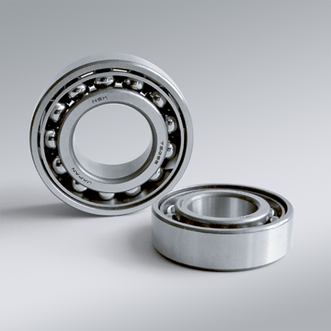
NSK NSK Angular Contact Ball Bearings ,A :Contact Angle of 30°, 7302AW ,D=15
NSK Angular Contact Ball Bearings ,A :Contact Angle of 30°, 7302AW ,D=15 Bearing Numbers Boundary Dimensions (mm) Basic Load Ratings (kN) Limiting Speeds (min-1) Factor f0 Mass (kg) approx. d D B r min. r1 min. Cr C0r Grease Oil 7302AW 15 42 13 1 0.6 13.4 7.1 13000 17000 ?€ 0.084 DESIGN, TYPES, AND FEATURES SINGLE-ROW ANGULAR CONTACT BALL BEARINGS Single-row angular contact ball bearings have a contact angle allowing them to sustain significant axial loads in one direction together with radial loads. Because of their design, when a radial load is applied, an axial force component is produced; therefore, two or more opposed bearings must be used. Since the rigidity of single-row angular contact ball bearings can be increased by preloading, they are often used in the main spindles of machine tools where high running accuracy is required (refer to Chapter 9 Preload on Page A192 for more information). Usually, the cages for angular contact ball bearings with a contact angle of 30° (designation A) or 40°(designation B) are made in accordance with Table 1, but depending on the application, machined synthetic-resin cages or molded polyamide-resin cages may also be used. The basic load ratings given in the bearing tables are based on standard cages. Though the figures in the bearing tables on Pages C086 to C101 for bearing bore diameters of 10 to 120 show bearings with single-shoulder inner rings, dual-shoulder bearings are also available. Please consult NSK for more detailed information. MATCHED ANGULAR CONTACT BALL BEARINGS The types and features of matched angular contact ball bearings are shown in Table 2. Table 2 Types and Features of Matched Angular Contact Ball Bearings Figure Arrangement Features Back-to-Back(DB)(Example)7208 A DB Radial loads and axial loads in both directions can be sustained. Since the distance between the effective load centers a0 is large, this type is suitable if moments are applied. Face-to-Face(DF)(Example)7208 B DF Radial loads and axial loads in both directions can be sustained. Compared with the DB Type, the distance between the effective load centers is small, so the capacity to sustain moments is inferior. Tandem(DT)(Example)7208 A DT Radial loads and axial loads in one direction can be sustained. Since two bearings share the axial load, this arrangement is used when the load in one direction is heavy. ?¡Formulation of Bearing Designations Single-Row Matched Angular Contact Ball Bearings ? Bearing type 7 : Single-row angular contact ball bearings, matched angular contact ball bearings ?¡Dimension Series 2 : 02 Series, 3 : 03 Series, 9 : 19 Series, 0 : 10 Series ?¢Bore number Less than 03, Bearing bore 00 : 10mm, 01 : 12mm, 02 : 15mm, 03 : 17mmOver 04, Bearing bore Bore number ×5 (mm) ?£Contact angle C : 15°, A5 : 25°, A : 30°, B : 40° ?¤Internal design EA : High Load Capacity ?¥Cage W : Pressed steel Cage, T85 : Machined brass cage (ball-guided),No designation : Machined brass cage (inner ring guided), TYN : Polyamide resin cage,T85 : Polyamide 46 resin cage, T7 : L-PPS resin cage ?¦Arrangement SU: Universal arrangement (single-row), DU : Universal arrangement (double-row),DB : Back-to-back arrangement, DF : Face-to-face arrangement, DT : Tandem arrangement ?§Preload / Axial internal clearance EL : Extra light preload, L : Light preload, M : Medium preload, H : Heavy preloadOmitted : CN clearance, C3 : Clearance greater than CN, C4 : Clearance greater than C3,CNB : CN Clearance equivalent (universal arrangement) DOUBLE-ROW ANGULAR CONTACT BALL BEARINGS Double-row angular contact ball bearings are essentially a back- to-back mounting of two single-row angular contact ball bearings, but their inner and outer rings are each integrated into one. These bearings can sustain axial loads in both directions and offer good capacity for sustaining moment loads. They are often used as fixed- end bearings and contain cages made of pressed steel. ?¡Formulation of Bearing Designations Double-Row Angular Contact Ball Bearings ? Bearing type 5 : Double-row angular contact ball bearings ?¡Dimension Series 2 : 02 Series 3: 03 Series ?¢Bore number 03 and under: 00 : 10mm, 01 : 12mm, 02 : 15mm, 03 : 17mm 04 and over: Bore diameter bore number ×5 (mm) ?£Internal design ZZ: Steel shield on both sides, DDU: Rubber contact seal on both sides VV: Rubber noncontact seal on both sides ?¤Seals/shields Z: Steel shield on one sides, DU: Rubber contact seal on one side, V: Rubber non-contact seal on one side ?¥Grease* NS7: NS HI-LUBE
$19.11
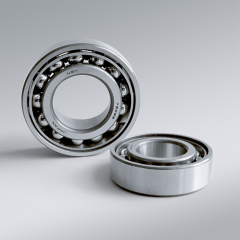
NSK NSK Angular Contact Ball Bearings ,A :Contact Angle of 30°, 7303AW ,D=17
NSK Angular Contact Ball Bearings ,A :Contact Angle of 30°, 7303AW ,D=17 Bearing Numbers Boundary Dimensions (mm) Basic Load Ratings (kN) Limiting Speeds (min-1) Factor f0 Mass (kg) approx. d D B r min. r1 min. Cr C0r Grease Oil 7303AW 17 47 14 1 0.6 15.9 8.65 11000 15000 ?€ 0.116 DESIGN, TYPES, AND FEATURES SINGLE-ROW ANGULAR CONTACT BALL BEARINGS Single-row angular contact ball bearings have a contact angle allowing them to sustain significant axial loads in one direction together with radial loads. Because of their design, when a radial load is applied, an axial force component is produced; therefore, two or more opposed bearings must be used. Since the rigidity of single-row angular contact ball bearings can be increased by preloading, they are often used in the main spindles of machine tools where high running accuracy is required (refer to Chapter 9 Preload on Page A192 for more information). Usually, the cages for angular contact ball bearings with a contact angle of 30° (designation A) or 40°(designation B) are made in accordance with Table 1, but depending on the application, machined synthetic-resin cages or molded polyamide-resin cages may also be used. The basic load ratings given in the bearing tables are based on standard cages. Though the figures in the bearing tables on Pages C086 to C101 for bearing bore diameters of 10 to 120 show bearings with single-shoulder inner rings, dual-shoulder bearings are also available. Please consult NSK for more detailed information. MATCHED ANGULAR CONTACT BALL BEARINGS The types and features of matched angular contact ball bearings are shown in Table 2. Table 2 Types and Features of Matched Angular Contact Ball Bearings Figure Arrangement Features Back-to-Back(DB)(Example)7208 A DB Radial loads and axial loads in both directions can be sustained. Since the distance between the effective load centers a0 is large, this type is suitable if moments are applied. Face-to-Face(DF)(Example)7208 B DF Radial loads and axial loads in both directions can be sustained. Compared with the DB Type, the distance between the effective load centers is small, so the capacity to sustain moments is inferior. Tandem(DT)(Example)7208 A DT Radial loads and axial loads in one direction can be sustained. Since two bearings share the axial load, this arrangement is used when the load in one direction is heavy. ?¡Formulation of Bearing Designations Single-Row Matched Angular Contact Ball Bearings ? Bearing type 7 : Single-row angular contact ball bearings, matched angular contact ball bearings ?¡Dimension Series 2 : 02 Series, 3 : 03 Series, 9 : 19 Series, 0 : 10 Series ?¢Bore number Less than 03, Bearing bore 00 : 10mm, 01 : 12mm, 02 : 15mm, 03 : 17mmOver 04, Bearing bore Bore number ×5 (mm) ?£Contact angle C : 15°, A5 : 25°, A : 30°, B : 40° ?¤Internal design EA : High Load Capacity ?¥Cage W : Pressed steel Cage, T85 : Machined brass cage (ball-guided),No designation : Machined brass cage (inner ring guided), TYN : Polyamide resin cage,T85 : Polyamide 46 resin cage, T7 : L-PPS resin cage ?¦Arrangement SU: Universal arrangement (single-row), DU : Universal arrangement (double-row),DB : Back-to-back arrangement, DF : Face-to-face arrangement, DT : Tandem arrangement ?§Preload / Axial internal clearance EL : Extra light preload, L : Light preload, M : Medium preload, H : Heavy preloadOmitted : CN clearance, C3 : Clearance greater than CN, C4 : Clearance greater than C3,CNB : CN Clearance equivalent (universal arrangement) DOUBLE-ROW ANGULAR CONTACT BALL BEARINGS Double-row angular contact ball bearings are essentially a back- to-back mounting of two single-row angular contact ball bearings, but their inner and outer rings are each integrated into one. These bearings can sustain axial loads in both directions and offer good capacity for sustaining moment loads. They are often used as fixed- end bearings and contain cages made of pressed steel. ?¡Formulation of Bearing Designations Double-Row Angular Contact Ball Bearings ? Bearing type 5 : Double-row angular contact ball bearings ?¡Dimension Series 2 : 02 Series 3: 03 Series ?¢Bore number 03 and under: 00 : 10mm, 01 : 12mm, 02 : 15mm, 03 : 17mm 04 and over: Bore diameter bore number ×5 (mm) ?£Internal design ZZ: Steel shield on both sides, DDU: Rubber contact seal on both sides VV: Rubber noncontact seal on both sides ?¤Seals/shields Z: Steel shield on one sides, DU: Rubber contact seal on one side, V: Rubber non-contact seal on one side ?¥Grease* NS7: NS HI-LUBE
$21.45
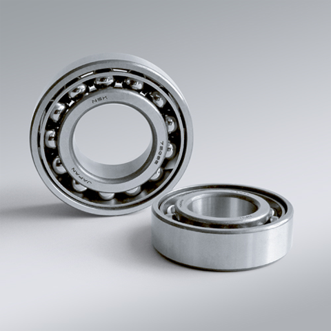
NSK NSK Angular Contact Ball Bearings ,A :Contact Angle of 30°, 7304AW ,D=20
NSK Angular Contact Ball Bearings ,A :Contact Angle of 30°, 7304AW ,D=20 Bearing Numbers Boundary Dimensions (mm) Basic Load Ratings (kN) Limiting Speeds (min-1) Factor f0 Mass (kg) approx. d D B r min. r1 min. Cr C0r Grease Oil 7304AW 20 52 15 1.1 0.6 18.7 10.4 10000 13000 ?€ 0.146 DESIGN, TYPES, AND FEATURES SINGLE-ROW ANGULAR CONTACT BALL BEARINGS Single-row angular contact ball bearings have a contact angle allowing them to sustain significant axial loads in one direction together with radial loads. Because of their design, when a radial load is applied, an axial force component is produced; therefore, two or more opposed bearings must be used. Since the rigidity of single-row angular contact ball bearings can be increased by preloading, they are often used in the main spindles of machine tools where high running accuracy is required (refer to Chapter 9 Preload on Page A192 for more information). Usually, the cages for angular contact ball bearings with a contact angle of 30° (designation A) or 40°(designation B) are made in accordance with Table 1, but depending on the application, machined synthetic-resin cages or molded polyamide-resin cages may also be used. The basic load ratings given in the bearing tables are based on standard cages. Though the figures in the bearing tables on Pages C086 to C101 for bearing bore diameters of 10 to 120 show bearings with single-shoulder inner rings, dual-shoulder bearings are also available. Please consult NSK for more detailed information. MATCHED ANGULAR CONTACT BALL BEARINGS The types and features of matched angular contact ball bearings are shown in Table 2. Table 2 Types and Features of Matched Angular Contact Ball Bearings Figure Arrangement Features Back-to-Back(DB)(Example)7208 A DB Radial loads and axial loads in both directions can be sustained. Since the distance between the effective load centers a0 is large, this type is suitable if moments are applied. Face-to-Face(DF)(Example)7208 B DF Radial loads and axial loads in both directions can be sustained. Compared with the DB Type, the distance between the effective load centers is small, so the capacity to sustain moments is inferior. Tandem(DT)(Example)7208 A DT Radial loads and axial loads in one direction can be sustained. Since two bearings share the axial load, this arrangement is used when the load in one direction is heavy. ?¡Formulation of Bearing Designations Single-Row Matched Angular Contact Ball Bearings ? Bearing type 7 : Single-row angular contact ball bearings, matched angular contact ball bearings ?¡Dimension Series 2 : 02 Series, 3 : 03 Series, 9 : 19 Series, 0 : 10 Series ?¢Bore number Less than 03, Bearing bore 00 : 10mm, 01 : 12mm, 02 : 15mm, 03 : 17mmOver 04, Bearing bore Bore number ×5 (mm) ?£Contact angle C : 15°, A5 : 25°, A : 30°, B : 40° ?¤Internal design EA : High Load Capacity ?¥Cage W : Pressed steel Cage, T85 : Machined brass cage (ball-guided),No designation : Machined brass cage (inner ring guided), TYN : Polyamide resin cage,T85 : Polyamide 46 resin cage, T7 : L-PPS resin cage ?¦Arrangement SU: Universal arrangement (single-row), DU : Universal arrangement (double-row),DB : Back-to-back arrangement, DF : Face-to-face arrangement, DT : Tandem arrangement ?§Preload / Axial internal clearance EL : Extra light preload, L : Light preload, M : Medium preload, H : Heavy preloadOmitted : CN clearance, C3 : Clearance greater than CN, C4 : Clearance greater than C3,CNB : CN Clearance equivalent (universal arrangement) DOUBLE-ROW ANGULAR CONTACT BALL BEARINGS Double-row angular contact ball bearings are essentially a back- to-back mounting of two single-row angular contact ball bearings, but their inner and outer rings are each integrated into one. These bearings can sustain axial loads in both directions and offer good capacity for sustaining moment loads. They are often used as fixed- end bearings and contain cages made of pressed steel. ?¡Formulation of Bearing Designations Double-Row Angular Contact Ball Bearings ? Bearing type 5 : Double-row angular contact ball bearings ?¡Dimension Series 2 : 02 Series 3: 03 Series ?¢Bore number 03 and under: 00 : 10mm, 01 : 12mm, 02 : 15mm, 03 : 17mm 04 and over: Bore diameter bore number ×5 (mm) ?£Internal design ZZ: Steel shield on both sides, DDU: Rubber contact seal on both sides VV: Rubber noncontact seal on both sides ?¤Seals/shields Z: Steel shield on one sides, DU: Rubber contact seal on one side, V: Rubber non-contact seal on one side ?¥Grease* NS7: NS HI-LUBE
$22.10
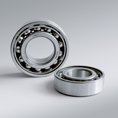
NSK NSK Angular Contact Ball Bearings ,A :Contact Angle of 30°, 7305AW ,D=25
NSK Angular Contact Ball Bearings ,A :Contact Angle of 30°, 7305AW ,D=25 Bearing Numbers Boundary Dimensions (mm) Basic Load Ratings (kN) Limiting Speeds (min-1) Factor f0 Mass (kg) approx. d D B r min. r1 min. Cr C0r Grease Oil 7305AW 25 62 17 1.1 0.6 26.4 15.8 8500 11000 ?€ 0.235 DESIGN, TYPES, AND FEATURES SINGLE-ROW ANGULAR CONTACT BALL BEARINGS Single-row angular contact ball bearings have a contact angle allowing them to sustain significant axial loads in one direction together with radial loads. Because of their design, when a radial load is applied, an axial force component is produced; therefore, two or more opposed bearings must be used. Since the rigidity of single-row angular contact ball bearings can be increased by preloading, they are often used in the main spindles of machine tools where high running accuracy is required (refer to Chapter 9 Preload on Page A192 for more information). Usually, the cages for angular contact ball bearings with a contact angle of 30° (designation A) or 40°(designation B) are made in accordance with Table 1, but depending on the application, machined synthetic-resin cages or molded polyamide-resin cages may also be used. The basic load ratings given in the bearing tables are based on standard cages. Though the figures in the bearing tables on Pages C086 to C101 for bearing bore diameters of 10 to 120 show bearings with single-shoulder inner rings, dual-shoulder bearings are also available. Please consult NSK for more detailed information. MATCHED ANGULAR CONTACT BALL BEARINGS The types and features of matched angular contact ball bearings are shown in Table 2. Table 2 Types and Features of Matched Angular Contact Ball Bearings Figure Arrangement Features Back-to-Back(DB)(Example)7208 A DB Radial loads and axial loads in both directions can be sustained. Since the distance between the effective load centers a0 is large, this type is suitable if moments are applied. Face-to-Face(DF)(Example)7208 B DF Radial loads and axial loads in both directions can be sustained. Compared with the DB Type, the distance between the effective load centers is small, so the capacity to sustain moments is inferior. Tandem(DT)(Example)7208 A DT Radial loads and axial loads in one direction can be sustained. Since two bearings share the axial load, this arrangement is used when the load in one direction is heavy. ?¡Formulation of Bearing Designations Single-Row Matched Angular Contact Ball Bearings ? Bearing type 7 : Single-row angular contact ball bearings, matched angular contact ball bearings ?¡Dimension Series 2 : 02 Series, 3 : 03 Series, 9 : 19 Series, 0 : 10 Series ?¢Bore number Less than 03, Bearing bore 00 : 10mm, 01 : 12mm, 02 : 15mm, 03 : 17mmOver 04, Bearing bore Bore number ×5 (mm) ?£Contact angle C : 15°, A5 : 25°, A : 30°, B : 40° ?¤Internal design EA : High Load Capacity ?¥Cage W : Pressed steel Cage, T85 : Machined brass cage (ball-guided),No designation : Machined brass cage (inner ring guided), TYN : Polyamide resin cage,T85 : Polyamide 46 resin cage, T7 : L-PPS resin cage ?¦Arrangement SU: Universal arrangement (single-row), DU : Universal arrangement (double-row),DB : Back-to-back arrangement, DF : Face-to-face arrangement, DT : Tandem arrangement ?§Preload / Axial internal clearance EL : Extra light preload, L : Light preload, M : Medium preload, H : Heavy preloadOmitted : CN clearance, C3 : Clearance greater than CN, C4 : Clearance greater than C3,CNB : CN Clearance equivalent (universal arrangement) DOUBLE-ROW ANGULAR CONTACT BALL BEARINGS Double-row angular contact ball bearings are essentially a back- to-back mounting of two single-row angular contact ball bearings, but their inner and outer rings are each integrated into one. These bearings can sustain axial loads in both directions and offer good capacity for sustaining moment loads. They are often used as fixed- end bearings and contain cages made of pressed steel. ?¡Formulation of Bearing Designations Double-Row Angular Contact Ball Bearings ? Bearing type 5 : Double-row angular contact ball bearings ?¡Dimension Series 2 : 02 Series 3: 03 Series ?¢Bore number 03 and under: 00 : 10mm, 01 : 12mm, 02 : 15mm, 03 : 17mm 04 and over: Bore diameter bore number ×5 (mm) ?£Internal design ZZ: Steel shield on both sides, DDU: Rubber contact seal on both sides VV: Rubber noncontact seal on both sides ?¤Seals/shields Z: Steel shield on one sides, DU: Rubber contact seal on one side, V: Rubber non-contact seal on one side ?¥Grease* NS7: NS HI-LUBE
$22.99
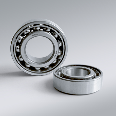
NSK NSK Angular Contact Ball Bearings ,A :Contact Angle of 30°, 7306AW ,D=30
NSK Angular Contact Ball Bearings ,A :Contact Angle of 30°, 7306AW ,D=30 Bearing Numbers Boundary Dimensions (mm) Basic Load Ratings (kN) Limiting Speeds (min-1) Factor f0 Mass (kg) approx. d D B r min. r1 min. Cr C0r Grease Oil 7306AW 30 72 19 1.1 0.6 33.5 20.9 7100 9500 ?€ 0.346 DESIGN, TYPES, AND FEATURES SINGLE-ROW ANGULAR CONTACT BALL BEARINGS Single-row angular contact ball bearings have a contact angle allowing them to sustain significant axial loads in one direction together with radial loads. Because of their design, when a radial load is applied, an axial force component is produced; therefore, two or more opposed bearings must be used. Since the rigidity of single-row angular contact ball bearings can be increased by preloading, they are often used in the main spindles of machine tools where high running accuracy is required (refer to Chapter 9 Preload on Page A192 for more information). Usually, the cages for angular contact ball bearings with a contact angle of 30° (designation A) or 40°(designation B) are made in accordance with Table 1, but depending on the application, machined synthetic-resin cages or molded polyamide-resin cages may also be used. The basic load ratings given in the bearing tables are based on standard cages. Though the figures in the bearing tables on Pages C086 to C101 for bearing bore diameters of 10 to 120 show bearings with single-shoulder inner rings, dual-shoulder bearings are also available. Please consult NSK for more detailed information. MATCHED ANGULAR CONTACT BALL BEARINGS The types and features of matched angular contact ball bearings are shown in Table 2. Table 2 Types and Features of Matched Angular Contact Ball Bearings Figure Arrangement Features Back-to-Back(DB)(Example)7208 A DB Radial loads and axial loads in both directions can be sustained. Since the distance between the effective load centers a0 is large, this type is suitable if moments are applied. Face-to-Face(DF)(Example)7208 B DF Radial loads and axial loads in both directions can be sustained. Compared with the DB Type, the distance between the effective load centers is small, so the capacity to sustain moments is inferior. Tandem(DT)(Example)7208 A DT Radial loads and axial loads in one direction can be sustained. Since two bearings share the axial load, this arrangement is used when the load in one direction is heavy. ?¡Formulation of Bearing Designations Single-Row Matched Angular Contact Ball Bearings ? Bearing type 7 : Single-row angular contact ball bearings, matched angular contact ball bearings ?¡Dimension Series 2 : 02 Series, 3 : 03 Series, 9 : 19 Series, 0 : 10 Series ?¢Bore number Less than 03, Bearing bore 00 : 10mm, 01 : 12mm, 02 : 15mm, 03 : 17mmOver 04, Bearing bore Bore number ×5 (mm) ?£Contact angle C : 15°, A5 : 25°, A : 30°, B : 40° ?¤Internal design EA : High Load Capacity ?¥Cage W : Pressed steel Cage, T85 : Machined brass cage (ball-guided),No designation : Machined brass cage (inner ring guided), TYN : Polyamide resin cage,T85 : Polyamide 46 resin cage, T7 : L-PPS resin cage ?¦Arrangement SU: Universal arrangement (single-row), DU : Universal arrangement (double-row),DB : Back-to-back arrangement, DF : Face-to-face arrangement, DT : Tandem arrangement ?§Preload / Axial internal clearance EL : Extra light preload, L : Light preload, M : Medium preload, H : Heavy preloadOmitted : CN clearance, C3 : Clearance greater than CN, C4 : Clearance greater than C3,CNB : CN Clearance equivalent (universal arrangement) DOUBLE-ROW ANGULAR CONTACT BALL BEARINGS Double-row angular contact ball bearings are essentially a back- to-back mounting of two single-row angular contact ball bearings, but their inner and outer rings are each integrated into one. These bearings can sustain axial loads in both directions and offer good capacity for sustaining moment loads. They are often used as fixed- end bearings and contain cages made of pressed steel. ?¡Formulation of Bearing Designations Double-Row Angular Contact Ball Bearings ? Bearing type 5 : Double-row angular contact ball bearings ?¡Dimension Series 2 : 02 Series 3: 03 Series ?¢Bore number 03 and under: 00 : 10mm, 01 : 12mm, 02 : 15mm, 03 : 17mm 04 and over: Bore diameter bore number ×5 (mm) ?£Internal design ZZ: Steel shield on both sides, DDU: Rubber contact seal on both sides VV: Rubber noncontact seal on both sides ?¤Seals/shields Z: Steel shield on one sides, DU: Rubber contact seal on one side, V: Rubber non-contact seal on one side ?¥Grease* NS7: NS HI-LUBE
$28.02
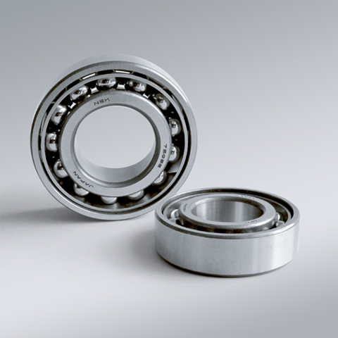
NSK NSK Angular Contact Ball Bearings ,A :Contact Angle of 30°, 7307AW ,D=35
NSK Angular Contact Ball Bearings ,A :Contact Angle of 30°, 7307AW ,D=35 Bearing Numbers Boundary Dimensions (mm) Basic Load Ratings (kN) Limiting Speeds (min-1) Factor f0 Mass (kg) approx. d D B r min. r1 min. Cr C0r Grease Oil 7307AW 35 80 21 1.5 1 40 26.3 6300 8500 ?€ 0.464 DESIGN, TYPES, AND FEATURES SINGLE-ROW ANGULAR CONTACT BALL BEARINGS Single-row angular contact ball bearings have a contact angle allowing them to sustain significant axial loads in one direction together with radial loads. Because of their design, when a radial load is applied, an axial force component is produced; therefore, two or more opposed bearings must be used. Since the rigidity of single-row angular contact ball bearings can be increased by preloading, they are often used in the main spindles of machine tools where high running accuracy is required (refer to Chapter 9 Preload on Page A192 for more information). Usually, the cages for angular contact ball bearings with a contact angle of 30° (designation A) or 40°(designation B) are made in accordance with Table 1, but depending on the application, machined synthetic-resin cages or molded polyamide-resin cages may also be used. The basic load ratings given in the bearing tables are based on standard cages. Though the figures in the bearing tables on Pages C086 to C101 for bearing bore diameters of 10 to 120 show bearings with single-shoulder inner rings, dual-shoulder bearings are also available. Please consult NSK for more detailed information. MATCHED ANGULAR CONTACT BALL BEARINGS The types and features of matched angular contact ball bearings are shown in Table 2. Table 2 Types and Features of Matched Angular Contact Ball Bearings Figure Arrangement Features Back-to-Back(DB)(Example)7208 A DB Radial loads and axial loads in both directions can be sustained. Since the distance between the effective load centers a0 is large, this type is suitable if moments are applied. Face-to-Face(DF)(Example)7208 B DF Radial loads and axial loads in both directions can be sustained. Compared with the DB Type, the distance between the effective load centers is small, so the capacity to sustain moments is inferior. Tandem(DT)(Example)7208 A DT Radial loads and axial loads in one direction can be sustained. Since two bearings share the axial load, this arrangement is used when the load in one direction is heavy. ?¡Formulation of Bearing Designations Single-Row Matched Angular Contact Ball Bearings ? Bearing type 7 : Single-row angular contact ball bearings, matched angular contact ball bearings ?¡Dimension Series 2 : 02 Series, 3 : 03 Series, 9 : 19 Series, 0 : 10 Series ?¢Bore number Less than 03, Bearing bore 00 : 10mm, 01 : 12mm, 02 : 15mm, 03 : 17mmOver 04, Bearing bore Bore number ×5 (mm) ?£Contact angle C : 15°, A5 : 25°, A : 30°, B : 40° ?¤Internal design EA : High Load Capacity ?¥Cage W : Pressed steel Cage, T85 : Machined brass cage (ball-guided),No designation : Machined brass cage (inner ring guided), TYN : Polyamide resin cage,T85 : Polyamide 46 resin cage, T7 : L-PPS resin cage ?¦Arrangement SU: Universal arrangement (single-row), DU : Universal arrangement (double-row),DB : Back-to-back arrangement, DF : Face-to-face arrangement, DT : Tandem arrangement ?§Preload / Axial internal clearance EL : Extra light preload, L : Light preload, M : Medium preload, H : Heavy preloadOmitted : CN clearance, C3 : Clearance greater than CN, C4 : Clearance greater than C3,CNB : CN Clearance equivalent (universal arrangement) DOUBLE-ROW ANGULAR CONTACT BALL BEARINGS Double-row angular contact ball bearings are essentially a back- to-back mounting of two single-row angular contact ball bearings, but their inner and outer rings are each integrated into one. These bearings can sustain axial loads in both directions and offer good capacity for sustaining moment loads. They are often used as fixed- end bearings and contain cages made of pressed steel. ?¡Formulation of Bearing Designations Double-Row Angular Contact Ball Bearings ? Bearing type 5 : Double-row angular contact ball bearings ?¡Dimension Series 2 : 02 Series 3: 03 Series ?¢Bore number 03 and under: 00 : 10mm, 01 : 12mm, 02 : 15mm, 03 : 17mm 04 and over: Bore diameter bore number ×5 (mm) ?£Internal design ZZ: Steel shield on both sides, DDU: Rubber contact seal on both sides VV: Rubber noncontact seal on both sides ?¤Seals/shields Z: Steel shield on one sides, DU: Rubber contact seal on one side, V: Rubber non-contact seal on one side ?¥Grease* NS7: NS HI-LUBE
$33.26
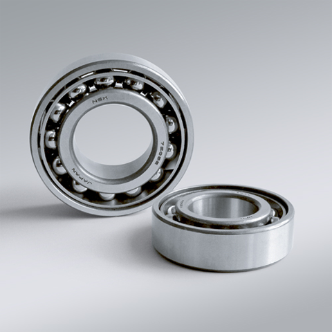
NSK NSK Angular Contact Ball Bearings ,A :Contact Angle of 30°, 7308AW ,D=40
NSK Angular Contact Ball Bearings ,A :Contact Angle of 30°, 7308AW ,D=40 Bearing Numbers Boundary Dimensions (mm) Basic Load Ratings (kN) Limiting Speeds (min-1) Factor f0 Mass (kg) approx. d D B r min. r1 min. Cr C0r Grease Oil 7308AW 40 90 23 1.5 1 49 33 5600 7500 ?€ 0.633 DESIGN, TYPES, AND FEATURES SINGLE-ROW ANGULAR CONTACT BALL BEARINGS Single-row angular contact ball bearings have a contact angle allowing them to sustain significant axial loads in one direction together with radial loads. Because of their design, when a radial load is applied, an axial force component is produced; therefore, two or more opposed bearings must be used. Since the rigidity of single-row angular contact ball bearings can be increased by preloading, they are often used in the main spindles of machine tools where high running accuracy is required (refer to Chapter 9 Preload on Page A192 for more information). Usually, the cages for angular contact ball bearings with a contact angle of 30° (designation A) or 40°(designation B) are made in accordance with Table 1, but depending on the application, machined synthetic-resin cages or molded polyamide-resin cages may also be used. The basic load ratings given in the bearing tables are based on standard cages. Though the figures in the bearing tables on Pages C086 to C101 for bearing bore diameters of 10 to 120 show bearings with single-shoulder inner rings, dual-shoulder bearings are also available. Please consult NSK for more detailed information. MATCHED ANGULAR CONTACT BALL BEARINGS The types and features of matched angular contact ball bearings are shown in Table 2. Table 2 Types and Features of Matched Angular Contact Ball Bearings Figure Arrangement Features Back-to-Back(DB)(Example)7208 A DB Radial loads and axial loads in both directions can be sustained. Since the distance between the effective load centers a0 is large, this type is suitable if moments are applied. Face-to-Face(DF)(Example)7208 B DF Radial loads and axial loads in both directions can be sustained. Compared with the DB Type, the distance between the effective load centers is small, so the capacity to sustain moments is inferior. Tandem(DT)(Example)7208 A DT Radial loads and axial loads in one direction can be sustained. Since two bearings share the axial load, this arrangement is used when the load in one direction is heavy. ?¡Formulation of Bearing Designations Single-Row Matched Angular Contact Ball Bearings ? Bearing type 7 : Single-row angular contact ball bearings, matched angular contact ball bearings ?¡Dimension Series 2 : 02 Series, 3 : 03 Series, 9 : 19 Series, 0 : 10 Series ?¢Bore number Less than 03, Bearing bore 00 : 10mm, 01 : 12mm, 02 : 15mm, 03 : 17mmOver 04, Bearing bore Bore number ×5 (mm) ?£Contact angle C : 15°, A5 : 25°, A : 30°, B : 40° ?¤Internal design EA : High Load Capacity ?¥Cage W : Pressed steel Cage, T85 : Machined brass cage (ball-guided),No designation : Machined brass cage (inner ring guided), TYN : Polyamide resin cage,T85 : Polyamide 46 resin cage, T7 : L-PPS resin cage ?¦Arrangement SU: Universal arrangement (single-row), DU : Universal arrangement (double-row),DB : Back-to-back arrangement, DF : Face-to-face arrangement, DT : Tandem arrangement ?§Preload / Axial internal clearance EL : Extra light preload, L : Light preload, M : Medium preload, H : Heavy preloadOmitted : CN clearance, C3 : Clearance greater than CN, C4 : Clearance greater than C3,CNB : CN Clearance equivalent (universal arrangement) DOUBLE-ROW ANGULAR CONTACT BALL BEARINGS Double-row angular contact ball bearings are essentially a back- to-back mounting of two single-row angular contact ball bearings, but their inner and outer rings are each integrated into one. These bearings can sustain axial loads in both directions and offer good capacity for sustaining moment loads. They are often used as fixed- end bearings and contain cages made of pressed steel. ?¡Formulation of Bearing Designations Double-Row Angular Contact Ball Bearings ? Bearing type 5 : Double-row angular contact ball bearings ?¡Dimension Series 2 : 02 Series 3: 03 Series ?¢Bore number 03 and under: 00 : 10mm, 01 : 12mm, 02 : 15mm, 03 : 17mm 04 and over: Bore diameter bore number ×5 (mm) ?£Internal design ZZ: Steel shield on both sides, DDU: Rubber contact seal on both sides VV: Rubber noncontact seal on both sides ?¤Seals/shields Z: Steel shield on one sides, DU: Rubber contact seal on one side, V: Rubber non-contact seal on one side ?¥Grease* NS7: NS HI-LUBE
$43.86
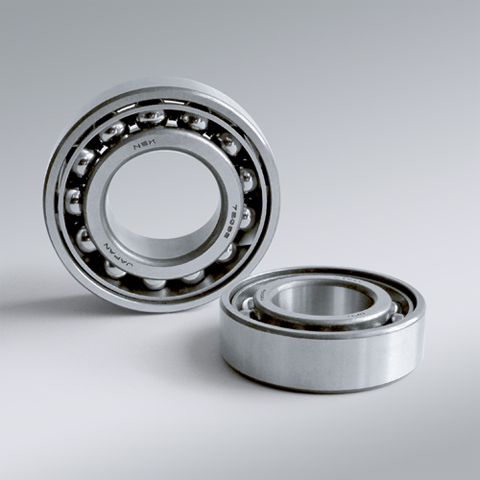
NSK NSK Angular Contact Ball Bearings ,A :Contact Angle of 30°, 7309AW ,D=45
NSK Angular Contact Ball Bearings ,A :Contact Angle of 30°, 7309AW ,D=45 Bearing Numbers Boundary Dimensions (mm) Basic Load Ratings (kN) Limiting Speeds (min-1) Factor f0 Mass (kg) approx. d D B r min. r1 min. Cr C0r Grease Oil 7309AW 45 100 25 1.5 1 63.5 43.5 5000 6700 ?€ 0.848 DESIGN, TYPES, AND FEATURES SINGLE-ROW ANGULAR CONTACT BALL BEARINGS Single-row angular contact ball bearings have a contact angle allowing them to sustain significant axial loads in one direction together with radial loads. Because of their design, when a radial load is applied, an axial force component is produced; therefore, two or more opposed bearings must be used. Since the rigidity of single-row angular contact ball bearings can be increased by preloading, they are often used in the main spindles of machine tools where high running accuracy is required (refer to Chapter 9 Preload on Page A192 for more information). Usually, the cages for angular contact ball bearings with a contact angle of 30° (designation A) or 40°(designation B) are made in accordance with Table 1, but depending on the application, machined synthetic-resin cages or molded polyamide-resin cages may also be used. The basic load ratings given in the bearing tables are based on standard cages. Though the figures in the bearing tables on Pages C086 to C101 for bearing bore diameters of 10 to 120 show bearings with single-shoulder inner rings, dual-shoulder bearings are also available. Please consult NSK for more detailed information. MATCHED ANGULAR CONTACT BALL BEARINGS The types and features of matched angular contact ball bearings are shown in Table 2. Table 2 Types and Features of Matched Angular Contact Ball Bearings Figure Arrangement Features Back-to-Back(DB)(Example)7208 A DB Radial loads and axial loads in both directions can be sustained. Since the distance between the effective load centers a0 is large, this type is suitable if moments are applied. Face-to-Face(DF)(Example)7208 B DF Radial loads and axial loads in both directions can be sustained. Compared with the DB Type, the distance between the effective load centers is small, so the capacity to sustain moments is inferior. Tandem(DT)(Example)7208 A DT Radial loads and axial loads in one direction can be sustained. Since two bearings share the axial load, this arrangement is used when the load in one direction is heavy. ?¡Formulation of Bearing Designations Single-Row Matched Angular Contact Ball Bearings ? Bearing type 7 : Single-row angular contact ball bearings, matched angular contact ball bearings ?¡Dimension Series 2 : 02 Series, 3 : 03 Series, 9 : 19 Series, 0 : 10 Series ?¢Bore number Less than 03, Bearing bore 00 : 10mm, 01 : 12mm, 02 : 15mm, 03 : 17mmOver 04, Bearing bore Bore number ×5 (mm) ?£Contact angle C : 15°, A5 : 25°, A : 30°, B : 40° ?¤Internal design EA : High Load Capacity ?¥Cage W : Pressed steel Cage, T85 : Machined brass cage (ball-guided),No designation : Machined brass cage (inner ring guided), TYN : Polyamide resin cage,T85 : Polyamide 46 resin cage, T7 : L-PPS resin cage ?¦Arrangement SU: Universal arrangement (single-row), DU : Universal arrangement (double-row),DB : Back-to-back arrangement, DF : Face-to-face arrangement, DT : Tandem arrangement ?§Preload / Axial internal clearance EL : Extra light preload, L : Light preload, M : Medium preload, H : Heavy preloadOmitted : CN clearance, C3 : Clearance greater than CN, C4 : Clearance greater than C3,CNB : CN Clearance equivalent (universal arrangement) DOUBLE-ROW ANGULAR CONTACT BALL BEARINGS Double-row angular contact ball bearings are essentially a back- to-back mounting of two single-row angular contact ball bearings, but their inner and outer rings are each integrated into one. These bearings can sustain axial loads in both directions and offer good capacity for sustaining moment loads. They are often used as fixed- end bearings and contain cages made of pressed steel. ?¡Formulation of Bearing Designations Double-Row Angular Contact Ball Bearings ? Bearing type 5 : Double-row angular contact ball bearings ?¡Dimension Series 2 : 02 Series 3: 03 Series ?¢Bore number 03 and under: 00 : 10mm, 01 : 12mm, 02 : 15mm, 03 : 17mm 04 and over: Bore diameter bore number ×5 (mm) ?£Internal design ZZ: Steel shield on both sides, DDU: Rubber contact seal on both sides VV: Rubber noncontact seal on both sides ?¤Seals/shields Z: Steel shield on one sides, DU: Rubber contact seal on one side, V: Rubber non-contact seal on one side ?¥Grease* NS7: NS HI-LUBE
$54.94
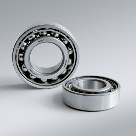
NSK NSK Angular Contact Ball Bearings ,A :Contact Angle of 30°, 7310AW ,D=50
NSK Angular Contact Ball Bearings ,A :Contact Angle of 30°, 7310AW ,D=50 Bearing Numbers Boundary Dimensions (mm) Basic Load Ratings (kN) Limiting Speeds (min-1) Factor f0 Mass (kg) approx. d D B r min. r1 min. Cr C0r Grease Oil 7310AW 50 110 27 2 1 74 52 4500 6000 ?€ 1.1 DESIGN, TYPES, AND FEATURES SINGLE-ROW ANGULAR CONTACT BALL BEARINGS Single-row angular contact ball bearings have a contact angle allowing them to sustain significant axial loads in one direction together with radial loads. Because of their design, when a radial load is applied, an axial force component is produced; therefore, two or more opposed bearings must be used. Since the rigidity of single-row angular contact ball bearings can be increased by preloading, they are often used in the main spindles of machine tools where high running accuracy is required (refer to Chapter 9 Preload on Page A192 for more information). Usually, the cages for angular contact ball bearings with a contact angle of 30° (designation A) or 40°(designation B) are made in accordance with Table 1, but depending on the application, machined synthetic-resin cages or molded polyamide-resin cages may also be used. The basic load ratings given in the bearing tables are based on standard cages. Though the figures in the bearing tables on Pages C086 to C101 for bearing bore diameters of 10 to 120 show bearings with single-shoulder inner rings, dual-shoulder bearings are also available. Please consult NSK for more detailed information. MATCHED ANGULAR CONTACT BALL BEARINGS The types and features of matched angular contact ball bearings are shown in Table 2. Table 2 Types and Features of Matched Angular Contact Ball Bearings Figure Arrangement Features Back-to-Back(DB)(Example)7208 A DB Radial loads and axial loads in both directions can be sustained. Since the distance between the effective load centers a0 is large, this type is suitable if moments are applied. Face-to-Face(DF)(Example)7208 B DF Radial loads and axial loads in both directions can be sustained. Compared with the DB Type, the distance between the effective load centers is small, so the capacity to sustain moments is inferior. Tandem(DT)(Example)7208 A DT Radial loads and axial loads in one direction can be sustained. Since two bearings share the axial load, this arrangement is used when the load in one direction is heavy. ?¡Formulation of Bearing Designations Single-Row Matched Angular Contact Ball Bearings ? Bearing type 7 : Single-row angular contact ball bearings, matched angular contact ball bearings ?¡Dimension Series 2 : 02 Series, 3 : 03 Series, 9 : 19 Series, 0 : 10 Series ?¢Bore number Less than 03, Bearing bore 00 : 10mm, 01 : 12mm, 02 : 15mm, 03 : 17mmOver 04, Bearing bore Bore number ×5 (mm) ?£Contact angle C : 15°, A5 : 25°, A : 30°, B : 40° ?¤Internal design EA : High Load Capacity ?¥Cage W : Pressed steel Cage, T85 : Machined brass cage (ball-guided),No designation : Machined brass cage (inner ring guided), TYN : Polyamide resin cage,T85 : Polyamide 46 resin cage, T7 : L-PPS resin cage ?¦Arrangement SU: Universal arrangement (single-row), DU : Universal arrangement (double-row),DB : Back-to-back arrangement, DF : Face-to-face arrangement, DT : Tandem arrangement ?§Preload / Axial internal clearance EL : Extra light preload, L : Light preload, M : Medium preload, H : Heavy preloadOmitted : CN clearance, C3 : Clearance greater than CN, C4 : Clearance greater than C3,CNB : CN Clearance equivalent (universal arrangement) DOUBLE-ROW ANGULAR CONTACT BALL BEARINGS Double-row angular contact ball bearings are essentially a back- to-back mounting of two single-row angular contact ball bearings, but their inner and outer rings are each integrated into one. These bearings can sustain axial loads in both directions and offer good capacity for sustaining moment loads. They are often used as fixed- end bearings and contain cages made of pressed steel. ?¡Formulation of Bearing Designations Double-Row Angular Contact Ball Bearings ? Bearing type 5 : Double-row angular contact ball bearings ?¡Dimension Series 2 : 02 Series 3: 03 Series ?¢Bore number 03 and under: 00 : 10mm, 01 : 12mm, 02 : 15mm, 03 : 17mm 04 and over: Bore diameter bore number ×5 (mm) ?£Internal design ZZ: Steel shield on both sides, DDU: Rubber contact seal on both sides VV: Rubber noncontact seal on both sides ?¤Seals/shields Z: Steel shield on one sides, DU: Rubber contact seal on one side, V: Rubber non-contact seal on one side ?¥Grease* NS7: NS HI-LUBE
$63.90
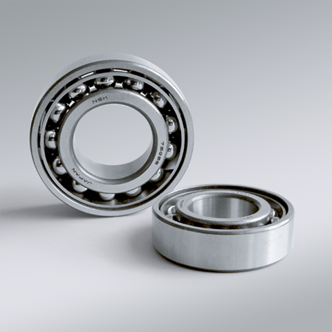
NSK NSK Angular Contact Ball Bearings ,A :Contact Angle of 30°, 7311AW ,D=55
NSK Angular Contact Ball Bearings ,A :Contact Angle of 30°, 7311AW ,D=55 Bearing Numbers Boundary Dimensions (mm) Basic Load Ratings (kN) Limiting Speeds (min-1) Factor f0 Mass (kg) approx. d D B r min. r1 min. Cr C0r Grease Oil 7311AW 55 120 29 2 1 86 61.5 4000 5600 ?€ 1.41 DESIGN, TYPES, AND FEATURES SINGLE-ROW ANGULAR CONTACT BALL BEARINGS Single-row angular contact ball bearings have a contact angle allowing them to sustain significant axial loads in one direction together with radial loads. Because of their design, when a radial load is applied, an axial force component is produced; therefore, two or more opposed bearings must be used. Since the rigidity of single-row angular contact ball bearings can be increased by preloading, they are often used in the main spindles of machine tools where high running accuracy is required (refer to Chapter 9 Preload on Page A192 for more information). Usually, the cages for angular contact ball bearings with a contact angle of 30° (designation A) or 40°(designation B) are made in accordance with Table 1, but depending on the application, machined synthetic-resin cages or molded polyamide-resin cages may also be used. The basic load ratings given in the bearing tables are based on standard cages. Though the figures in the bearing tables on Pages C086 to C101 for bearing bore diameters of 10 to 120 show bearings with single-shoulder inner rings, dual-shoulder bearings are also available. Please consult NSK for more detailed information. MATCHED ANGULAR CONTACT BALL BEARINGS The types and features of matched angular contact ball bearings are shown in Table 2. Table 2 Types and Features of Matched Angular Contact Ball Bearings Figure Arrangement Features Back-to-Back(DB)(Example)7208 A DB Radial loads and axial loads in both directions can be sustained. Since the distance between the effective load centers a0 is large, this type is suitable if moments are applied. Face-to-Face(DF)(Example)7208 B DF Radial loads and axial loads in both directions can be sustained. Compared with the DB Type, the distance between the effective load centers is small, so the capacity to sustain moments is inferior. Tandem(DT)(Example)7208 A DT Radial loads and axial loads in one direction can be sustained. Since two bearings share the axial load, this arrangement is used when the load in one direction is heavy. ?¡Formulation of Bearing Designations Single-Row Matched Angular Contact Ball Bearings ? Bearing type 7 : Single-row angular contact ball bearings, matched angular contact ball bearings ?¡Dimension Series 2 : 02 Series, 3 : 03 Series, 9 : 19 Series, 0 : 10 Series ?¢Bore number Less than 03, Bearing bore 00 : 10mm, 01 : 12mm, 02 : 15mm, 03 : 17mmOver 04, Bearing bore Bore number ×5 (mm) ?£Contact angle C : 15°, A5 : 25°, A : 30°, B : 40° ?¤Internal design EA : High Load Capacity ?¥Cage W : Pressed steel Cage, T85 : Machined brass cage (ball-guided),No designation : Machined brass cage (inner ring guided), TYN : Polyamide resin cage,T85 : Polyamide 46 resin cage, T7 : L-PPS resin cage ?¦Arrangement SU: Universal arrangement (single-row), DU : Universal arrangement (double-row),DB : Back-to-back arrangement, DF : Face-to-face arrangement, DT : Tandem arrangement ?§Preload / Axial internal clearance EL : Extra light preload, L : Light preload, M : Medium preload, H : Heavy preloadOmitted : CN clearance, C3 : Clearance greater than CN, C4 : Clearance greater than C3,CNB : CN Clearance equivalent (universal arrangement) DOUBLE-ROW ANGULAR CONTACT BALL BEARINGS Double-row angular contact ball bearings are essentially a back- to-back mounting of two single-row angular contact ball bearings, but their inner and outer rings are each integrated into one. These bearings can sustain axial loads in both directions and offer good capacity for sustaining moment loads. They are often used as fixed- end bearings and contain cages made of pressed steel. ?¡Formulation of Bearing Designations Double-Row Angular Contact Ball Bearings ? Bearing type 5 : Double-row angular contact ball bearings ?¡Dimension Series 2 : 02 Series 3: 03 Series ?¢Bore number 03 and under: 00 : 10mm, 01 : 12mm, 02 : 15mm, 03 : 17mm 04 and over: Bore diameter bore number ×5 (mm) ?£Internal design ZZ: Steel shield on both sides, DDU: Rubber contact seal on both sides VV: Rubber noncontact seal on both sides ?¤Seals/shields Z: Steel shield on one sides, DU: Rubber contact seal on one side, V: Rubber non-contact seal on one side ?¥Grease* NS7: NS HI-LUBE
$76.26

NSK NSK Angular Contact Ball Bearings ,A :Contact Angle of 30°, 7312AW ,D=60
NSK Angular Contact Ball Bearings ,A :Contact Angle of 30°, 7312AW ,D=60 Bearing Numbers Boundary Dimensions (mm) Basic Load Ratings (kN) Limiting Speeds (min-1) Factor f0 Mass (kg) approx. d D B r min. r1 min. Cr C0r Grease Oil 7312AW 60 130 31 2.1 1.1 98 71.5 3800 5000 ?€ 1.74 DESIGN, TYPES, AND FEATURES SINGLE-ROW ANGULAR CONTACT BALL BEARINGS Single-row angular contact ball bearings have a contact angle allowing them to sustain significant axial loads in one direction together with radial loads. Because of their design, when a radial load is applied, an axial force component is produced; therefore, two or more opposed bearings must be used. Since the rigidity of single-row angular contact ball bearings can be increased by preloading, they are often used in the main spindles of machine tools where high running accuracy is required (refer to Chapter 9 Preload on Page A192 for more information). Usually, the cages for angular contact ball bearings with a contact angle of 30° (designation A) or 40°(designation B) are made in accordance with Table 1, but depending on the application, machined synthetic-resin cages or molded polyamide-resin cages may also be used. The basic load ratings given in the bearing tables are based on standard cages. Though the figures in the bearing tables on Pages C086 to C101 for bearing bore diameters of 10 to 120 show bearings with single-shoulder inner rings, dual-shoulder bearings are also available. Please consult NSK for more detailed information. MATCHED ANGULAR CONTACT BALL BEARINGS The types and features of matched angular contact ball bearings are shown in Table 2. Table 2 Types and Features of Matched Angular Contact Ball Bearings Figure Arrangement Features Back-to-Back(DB)(Example)7208 A DB Radial loads and axial loads in both directions can be sustained. Since the distance between the effective load centers a0 is large, this type is suitable if moments are applied. Face-to-Face(DF)(Example)7208 B DF Radial loads and axial loads in both directions can be sustained. Compared with the DB Type, the distance between the effective load centers is small, so the capacity to sustain moments is inferior. Tandem(DT)(Example)7208 A DT Radial loads and axial loads in one direction can be sustained. Since two bearings share the axial load, this arrangement is used when the load in one direction is heavy. ?¡Formulation of Bearing Designations Single-Row Matched Angular Contact Ball Bearings ? Bearing type 7 : Single-row angular contact ball bearings, matched angular contact ball bearings ?¡Dimension Series 2 : 02 Series, 3 : 03 Series, 9 : 19 Series, 0 : 10 Series ?¢Bore number Less than 03, Bearing bore 00 : 10mm, 01 : 12mm, 02 : 15mm, 03 : 17mmOver 04, Bearing bore Bore number ×5 (mm) ?£Contact angle C : 15°, A5 : 25°, A : 30°, B : 40° ?¤Internal design EA : High Load Capacity ?¥Cage W : Pressed steel Cage, T85 : Machined brass cage (ball-guided),No designation : Machined brass cage (inner ring guided), TYN : Polyamide resin cage,T85 : Polyamide 46 resin cage, T7 : L-PPS resin cage ?¦Arrangement SU: Universal arrangement (single-row), DU : Universal arrangement (double-row),DB : Back-to-back arrangement, DF : Face-to-face arrangement, DT : Tandem arrangement ?§Preload / Axial internal clearance EL : Extra light preload, L : Light preload, M : Medium preload, H : Heavy preloadOmitted : CN clearance, C3 : Clearance greater than CN, C4 : Clearance greater than C3,CNB : CN Clearance equivalent (universal arrangement) DOUBLE-ROW ANGULAR CONTACT BALL BEARINGS Double-row angular contact ball bearings are essentially a back- to-back mounting of two single-row angular contact ball bearings, but their inner and outer rings are each integrated into one. These bearings can sustain axial loads in both directions and offer good capacity for sustaining moment loads. They are often used as fixed- end bearings and contain cages made of pressed steel. ?¡Formulation of Bearing Designations Double-Row Angular Contact Ball Bearings ? Bearing type 5 : Double-row angular contact ball bearings ?¡Dimension Series 2 : 02 Series 3: 03 Series ?¢Bore number 03 and under: 00 : 10mm, 01 : 12mm, 02 : 15mm, 03 : 17mm 04 and over: Bore diameter bore number ×5 (mm) ?£Internal design ZZ: Steel shield on both sides, DDU: Rubber contact seal on both sides VV: Rubber noncontact seal on both sides ?¤Seals/shields Z: Steel shield on one sides, DU: Rubber contact seal on one side, V: Rubber non-contact seal on one side ?¥Grease* NS7: NS HI-LUBE
$103.43

NSK NSK Angular Contact Ball Bearings ,A :Contact Angle of 30°, 7313AW ,D=65
NSK Angular Contact Ball Bearings ,A :Contact Angle of 30°, 7313AW ,D=65 Bearing Numbers Boundary Dimensions (mm) Basic Load Ratings (kN) Limiting Speeds (min-1) Factor f0 Mass (kg) approx. d D B r min. r1 min. Cr C0r Grease Oil 7313AW 65 140 33 2.1 1.1 111 82 3600 4800 ?€ 2.12 DESIGN, TYPES, AND FEATURES SINGLE-ROW ANGULAR CONTACT BALL BEARINGS Single-row angular contact ball bearings have a contact angle allowing them to sustain significant axial loads in one direction together with radial loads. Because of their design, when a radial load is applied, an axial force component is produced; therefore, two or more opposed bearings must be used. Since the rigidity of single-row angular contact ball bearings can be increased by preloading, they are often used in the main spindles of machine tools where high running accuracy is required (refer to Chapter 9 Preload on Page A192 for more information). Usually, the cages for angular contact ball bearings with a contact angle of 30° (designation A) or 40°(designation B) are made in accordance with Table 1, but depending on the application, machined synthetic-resin cages or molded polyamide-resin cages may also be used. The basic load ratings given in the bearing tables are based on standard cages. Though the figures in the bearing tables on Pages C086 to C101 for bearing bore diameters of 10 to 120 show bearings with single-shoulder inner rings, dual-shoulder bearings are also available. Please consult NSK for more detailed information. MATCHED ANGULAR CONTACT BALL BEARINGS The types and features of matched angular contact ball bearings are shown in Table 2. Table 2 Types and Features of Matched Angular Contact Ball Bearings Figure Arrangement Features Back-to-Back(DB)(Example)7208 A DB Radial loads and axial loads in both directions can be sustained. Since the distance between the effective load centers a0 is large, this type is suitable if moments are applied. Face-to-Face(DF)(Example)7208 B DF Radial loads and axial loads in both directions can be sustained. Compared with the DB Type, the distance between the effective load centers is small, so the capacity to sustain moments is inferior. Tandem(DT)(Example)7208 A DT Radial loads and axial loads in one direction can be sustained. Since two bearings share the axial load, this arrangement is used when the load in one direction is heavy. ?¡Formulation of Bearing Designations Single-Row Matched Angular Contact Ball Bearings ? Bearing type 7 : Single-row angular contact ball bearings, matched angular contact ball bearings ?¡Dimension Series 2 : 02 Series, 3 : 03 Series, 9 : 19 Series, 0 : 10 Series ?¢Bore number Less than 03, Bearing bore 00 : 10mm, 01 : 12mm, 02 : 15mm, 03 : 17mmOver 04, Bearing bore Bore number ×5 (mm) ?£Contact angle C : 15°, A5 : 25°, A : 30°, B : 40° ?¤Internal design EA : High Load Capacity ?¥Cage W : Pressed steel Cage, T85 : Machined brass cage (ball-guided),No designation : Machined brass cage (inner ring guided), TYN : Polyamide resin cage,T85 : Polyamide 46 resin cage, T7 : L-PPS resin cage ?¦Arrangement SU: Universal arrangement (single-row), DU : Universal arrangement (double-row),DB : Back-to-back arrangement, DF : Face-to-face arrangement, DT : Tandem arrangement ?§Preload / Axial internal clearance EL : Extra light preload, L : Light preload, M : Medium preload, H : Heavy preloadOmitted : CN clearance, C3 : Clearance greater than CN, C4 : Clearance greater than C3,CNB : CN Clearance equivalent (universal arrangement) DOUBLE-ROW ANGULAR CONTACT BALL BEARINGS Double-row angular contact ball bearings are essentially a back- to-back mounting of two single-row angular contact ball bearings, but their inner and outer rings are each integrated into one. These bearings can sustain axial loads in both directions and offer good capacity for sustaining moment loads. They are often used as fixed- end bearings and contain cages made of pressed steel. ?¡Formulation of Bearing Designations Double-Row Angular Contact Ball Bearings ? Bearing type 5 : Double-row angular contact ball bearings ?¡Dimension Series 2 : 02 Series 3: 03 Series ?¢Bore number 03 and under: 00 : 10mm, 01 : 12mm, 02 : 15mm, 03 : 17mm 04 and over: Bore diameter bore number ×5 (mm) ?£Internal design ZZ: Steel shield on both sides, DDU: Rubber contact seal on both sides VV: Rubber noncontact seal on both sides ?¤Seals/shields Z: Steel shield on one sides, DU: Rubber contact seal on one side, V: Rubber non-contact seal on one side ?¥Grease* NS7: NS HI-LUBE
$139.18

NSK NSK Angular Contact Ball Bearings ,A :Contact Angle of 30°, 7314AW ,D=70
NSK Angular Contact Ball Bearings ,A :Contact Angle of 30°, 7314AW ,D=70 Bearing Numbers Boundary Dimensions (mm) Basic Load Ratings (kN) Limiting Speeds (min-1) Factor f0 Mass (kg) approx. d D B r min. r1 min. Cr C0r Grease Oil 7314AW 70 150 35 2.1 1.1 125 93.5 3200 4300 ?€ 2.6 DESIGN, TYPES, AND FEATURES SINGLE-ROW ANGULAR CONTACT BALL BEARINGS Single-row angular contact ball bearings have a contact angle allowing them to sustain significant axial loads in one direction together with radial loads. Because of their design, when a radial load is applied, an axial force component is produced; therefore, two or more opposed bearings must be used. Since the rigidity of single-row angular contact ball bearings can be increased by preloading, they are often used in the main spindles of machine tools where high running accuracy is required (refer to Chapter 9 Preload on Page A192 for more information). Usually, the cages for angular contact ball bearings with a contact angle of 30° (designation A) or 40°(designation B) are made in accordance with Table 1, but depending on the application, machined synthetic-resin cages or molded polyamide-resin cages may also be used. The basic load ratings given in the bearing tables are based on standard cages. Though the figures in the bearing tables on Pages C086 to C101 for bearing bore diameters of 10 to 120 show bearings with single-shoulder inner rings, dual-shoulder bearings are also available. Please consult NSK for more detailed information. MATCHED ANGULAR CONTACT BALL BEARINGS The types and features of matched angular contact ball bearings are shown in Table 2. Table 2 Types and Features of Matched Angular Contact Ball Bearings Figure Arrangement Features Back-to-Back(DB)(Example)7208 A DB Radial loads and axial loads in both directions can be sustained. Since the distance between the effective load centers a0 is large, this type is suitable if moments are applied. Face-to-Face(DF)(Example)7208 B DF Radial loads and axial loads in both directions can be sustained. Compared with the DB Type, the distance between the effective load centers is small, so the capacity to sustain moments is inferior. Tandem(DT)(Example)7208 A DT Radial loads and axial loads in one direction can be sustained. Since two bearings share the axial load, this arrangement is used when the load in one direction is heavy. ?¡Formulation of Bearing Designations Single-Row Matched Angular Contact Ball Bearings ? Bearing type 7 : Single-row angular contact ball bearings, matched angular contact ball bearings ?¡Dimension Series 2 : 02 Series, 3 : 03 Series, 9 : 19 Series, 0 : 10 Series ?¢Bore number Less than 03, Bearing bore 00 : 10mm, 01 : 12mm, 02 : 15mm, 03 : 17mmOver 04, Bearing bore Bore number ×5 (mm) ?£Contact angle C : 15°, A5 : 25°, A : 30°, B : 40° ?¤Internal design EA : High Load Capacity ?¥Cage W : Pressed steel Cage, T85 : Machined brass cage (ball-guided),No designation : Machined brass cage (inner ring guided), TYN : Polyamide resin cage,T85 : Polyamide 46 resin cage, T7 : L-PPS resin cage ?¦Arrangement SU: Universal arrangement (single-row), DU : Universal arrangement (double-row),DB : Back-to-back arrangement, DF : Face-to-face arrangement, DT : Tandem arrangement ?§Preload / Axial internal clearance EL : Extra light preload, L : Light preload, M : Medium preload, H : Heavy preloadOmitted : CN clearance, C3 : Clearance greater than CN, C4 : Clearance greater than C3,CNB : CN Clearance equivalent (universal arrangement) DOUBLE-ROW ANGULAR CONTACT BALL BEARINGS Double-row angular contact ball bearings are essentially a back- to-back mounting of two single-row angular contact ball bearings, but their inner and outer rings are each integrated into one. These bearings can sustain axial loads in both directions and offer good capacity for sustaining moment loads. They are often used as fixed- end bearings and contain cages made of pressed steel. ?¡Formulation of Bearing Designations Double-Row Angular Contact Ball Bearings ? Bearing type 5 : Double-row angular contact ball bearings ?¡Dimension Series 2 : 02 Series 3: 03 Series ?¢Bore number 03 and under: 00 : 10mm, 01 : 12mm, 02 : 15mm, 03 : 17mm 04 and over: Bore diameter bore number ×5 (mm) ?£Internal design ZZ: Steel shield on both sides, DDU: Rubber contact seal on both sides VV: Rubber noncontact seal on both sides ?¤Seals/shields Z: Steel shield on one sides, DU: Rubber contact seal on one side, V: Rubber non-contact seal on one side ?¥Grease* NS7: NS HI-LUBE
$161.54

NSK NSK Angular Contact Ball Bearings ,A :Contact Angle of 30°, 7315AW ,D=75
NSK Angular Contact Ball Bearings ,A :Contact Angle of 30°, 7315AW ,D=75 Bearing Numbers Boundary Dimensions (mm) Basic Load Ratings (kN) Limiting Speeds (min-1) Factor f0 Mass (kg) approx. d D B r min. r1 min. Cr C0r Grease Oil 7315AW 75 160 37 2.1 1.1 136 106 3000 4000 ?€ 3.13 DESIGN, TYPES, AND FEATURES SINGLE-ROW ANGULAR CONTACT BALL BEARINGS Single-row angular contact ball bearings have a contact angle allowing them to sustain significant axial loads in one direction together with radial loads. Because of their design, when a radial load is applied, an axial force component is produced; therefore, two or more opposed bearings must be used. Since the rigidity of single-row angular contact ball bearings can be increased by preloading, they are often used in the main spindles of machine tools where high running accuracy is required (refer to Chapter 9 Preload on Page A192 for more information). Usually, the cages for angular contact ball bearings with a contact angle of 30° (designation A) or 40°(designation B) are made in accordance with Table 1, but depending on the application, machined synthetic-resin cages or molded polyamide-resin cages may also be used. The basic load ratings given in the bearing tables are based on standard cages. Though the figures in the bearing tables on Pages C086 to C101 for bearing bore diameters of 10 to 120 show bearings with single-shoulder inner rings, dual-shoulder bearings are also available. Please consult NSK for more detailed information. MATCHED ANGULAR CONTACT BALL BEARINGS The types and features of matched angular contact ball bearings are shown in Table 2. Table 2 Types and Features of Matched Angular Contact Ball Bearings Figure Arrangement Features Back-to-Back(DB)(Example)7208 A DB Radial loads and axial loads in both directions can be sustained. Since the distance between the effective load centers a0 is large, this type is suitable if moments are applied. Face-to-Face(DF)(Example)7208 B DF Radial loads and axial loads in both directions can be sustained. Compared with the DB Type, the distance between the effective load centers is small, so the capacity to sustain moments is inferior. Tandem(DT)(Example)7208 A DT Radial loads and axial loads in one direction can be sustained. Since two bearings share the axial load, this arrangement is used when the load in one direction is heavy. ?¡Formulation of Bearing Designations Single-Row Matched Angular Contact Ball Bearings ? Bearing type 7 : Single-row angular contact ball bearings, matched angular contact ball bearings ?¡Dimension Series 2 : 02 Series, 3 : 03 Series, 9 : 19 Series, 0 : 10 Series ?¢Bore number Less than 03, Bearing bore 00 : 10mm, 01 : 12mm, 02 : 15mm, 03 : 17mmOver 04, Bearing bore Bore number ×5 (mm) ?£Contact angle C : 15°, A5 : 25°, A : 30°, B : 40° ?¤Internal design EA : High Load Capacity ?¥Cage W : Pressed steel Cage, T85 : Machined brass cage (ball-guided),No designation : Machined brass cage (inner ring guided), TYN : Polyamide resin cage,T85 : Polyamide 46 resin cage, T7 : L-PPS resin cage ?¦Arrangement SU: Universal arrangement (single-row), DU : Universal arrangement (double-row),DB : Back-to-back arrangement, DF : Face-to-face arrangement, DT : Tandem arrangement ?§Preload / Axial internal clearance EL : Extra light preload, L : Light preload, M : Medium preload, H : Heavy preloadOmitted : CN clearance, C3 : Clearance greater than CN, C4 : Clearance greater than C3,CNB : CN Clearance equivalent (universal arrangement) DOUBLE-ROW ANGULAR CONTACT BALL BEARINGS Double-row angular contact ball bearings are essentially a back- to-back mounting of two single-row angular contact ball bearings, but their inner and outer rings are each integrated into one. These bearings can sustain axial loads in both directions and offer good capacity for sustaining moment loads. They are often used as fixed- end bearings and contain cages made of pressed steel. ?¡Formulation of Bearing Designations Double-Row Angular Contact Ball Bearings ? Bearing type 5 : Double-row angular contact ball bearings ?¡Dimension Series 2 : 02 Series 3: 03 Series ?¢Bore number 03 and under: 00 : 10mm, 01 : 12mm, 02 : 15mm, 03 : 17mm 04 and over: Bore diameter bore number ×5 (mm) ?£Internal design ZZ: Steel shield on both sides, DDU: Rubber contact seal on both sides VV: Rubber noncontact seal on both sides ?¤Seals/shields Z: Steel shield on one sides, DU: Rubber contact seal on one side, V: Rubber non-contact seal on one side ?¥Grease* NS7: NS HI-LUBE
$215.37


